Electrothermal drive-based stepping micro-rotation device
An electrothermal drive, micro-rotation technology, applied in the direction of electromechanical devices, electrical components, etc., can solve the problems of difficult to reach directly, the conversion structure is not suitable for the motion conversion of micro-displacement actuators, etc., and achieves easy control, simple structure, and high output efficiency. Effect
- Summary
- Abstract
- Description
- Claims
- Application Information
AI Technical Summary
Problems solved by technology
Method used
Image
Examples
Embodiment 1
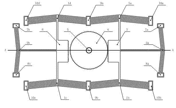
[0021] see figure 1 and figure 2 , the stepping and micro-rotating device driven by electric heat, including a driving part and a conversion transmission part, is characterized in that:
[0022] 1) The driving part includes two main actuators (1a, 1b and 1d, 1c) arranged horizontally on the left and right sides and one engagement control actuator (2b, 2a) on the left and right sides respectively , the four main actuators (1a, 1b and 1d, 1c) on the left and right sides are respectively composed of six V-shaped electrothermal silicon microactuators in series, and the ends are respectively connected to two negative electrodes (9a, 9b) and four positive electrodes (10a, 10b and 10c, 10d); the two meshing control actuators (2b, 2a) on the left and right sides are respectively composed of three V-shaped electrothermal silicon microactuators in series, and the ends Connect two negative electrodes (7b, 7a) and two positive electrodes (8b, 8a) respectively;
[0023] 2) The conversi...
Embodiment 2
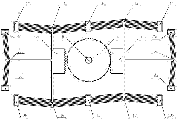
[0025] see image 3 , the level of this embodiment is the same as that of Embodiment 1, and the special feature is that: the driving part and the conversion transmission part are prepared on the nitride layer of the silicon substrate, there is a fixed structure layer Poly0 on the nitride layer, and there is a fixed structure layer Poly0 on the Poly0 The structural layer Poly2 constitutes the gear shaft (5), the active structural layer Poly1 on Poly0 constitutes the gear (4), the two racks (6, 3) and the meshing control actuators (2b, 2a).
Embodiment 3
[0027] In the switching device, the rack 3 meshes with the gear 4 in the initial state, the electrodes 7 and 8 supply power to the meshing control actuator 2 , and the electrodes 9 and 10 supply power to the active actuator 1 .
[0028] See attached figure 1 , after the electrodes 9a, 9b and 10a, 10b, 10c, 10d are simultaneously applied with a suitable voltage, the active actuators 1a, 1b, 1c, and 1d have currents passing through them, and the actuators are simultaneously upward under the action of resistance thermal stress. The movement drives the racks 3 and 6 to move upwards. Under the action of the racks 3, the gear 4 rotates counterclockwise at a certain angle; then the electrodes 7a, 8a and 7b, 8b are energized, and the meshing control actuators 2a, 2b have current passing through them. Movement to the right under the action of resistance thermal stress, rack 3 is out of mesh with gear 4, rack 6 is in mesh with gear 4; electrodes 9a, 9b and 10a, 10b, 10c, 10d are powered...
PUM
 Abstract
Description
Claims
Application Information
 - R&D
- Intellectual Property
- Life Sciences
- Materials
- Tech Scout
- Unparalleled Data Quality
- Higher Quality Content
- 60% Fewer Hallucinations
Browse by: Latest US Patents, China's latest patents, Technical Efficacy Thesaurus, Application Domain, Technology Topic, Popular Technical Reports.
© 2025 PatSnap. All rights reserved.Legal|Privacy policy|Modern Slavery Act Transparency Statement|Sitemap|About US| Contact US: help@patsnap.com


