Cutting module and full-automatic laser pipe cutting machine

A technology of cutting mechanism and cutting frame, which is applied to laser welding equipment, tubular objects, and other household appliances, etc., which can solve the problems of troublesome loading, long positioning time, and low positioning accuracy, so as to realize automatic loading and improve loading Efficiency, precision, reliable and solid effect

Active Publication Date: 2021-01-12
CHONGQING WANCHONGSHAN INTELLIGENT TECH CO LTD
View PDF7 Cites 2 Cited by
  • Summary
  • Abstract
  • Description
  • Claims
  • Application Information

AI Technical Summary

Problems solved by technology

[0003] 1. Feeding is troublesome. Since the long pipe must pass through the round hole, manual loading is required most of the time, which results in relatively low efficiency and serious obstacles to the design of subsequent fully automated processing technologies.
[0004] 2. The positioning accuracy is not high when the small trailer drives the long pipe to move along its axial direction. Considering that the long pipe is generally more than four meters in length, it will obviously cause greater manufacturing difficulty if the lead screw is used to drive the trolley, and Under the requirement of high precision, the lead screw must have relatively high transmission accuracy, and the cost is very high. In addition, the support and coaxiality of the lead screw are also difficult problems to solve.
If the chain drive is used, although the cost is low and the structure is simple, the positioning accuracy is low and the positioning time is long, which cannot meet the requirements of high-precision cutting
[0005] 3. Continuous feeding cannot be realized by using a small trailer, that is, loading can only be carried out after each long pipe is cut, and the loading time is relatively long, because it involves the process of clamping and axial positioning
Therefore, the way of small trailers cannot break through the current processing efficiency

Method used


Image

  • Cutting module and full-automatic laser pipe cutting machine
  • Cutting module and full-automatic laser pipe cutting machine
  • Cutting module and full-automatic laser pipe cutting machine

Examples


Embodiment Construction

[0028] The following will clearly and completely describe the technical solutions in the embodiments of the present invention with reference to the drawings in the embodiments of the present invention.

[0029] In describing the present invention, it should be understood that the terms "upper", "lower", "front", "rear", "left", "right", "top", "bottom", "inner", " The orientation or positional relationship indicated by "outside", etc. is based on the orientation or positional relationship shown in the drawings, and is only for the convenience of describing the present invention and simplifying the description, rather than indicating or implying that the referred device or element must have a specific orientation, so as to Specific orientation configurations and operations, therefore, are not to be construed as limitations on the invention.

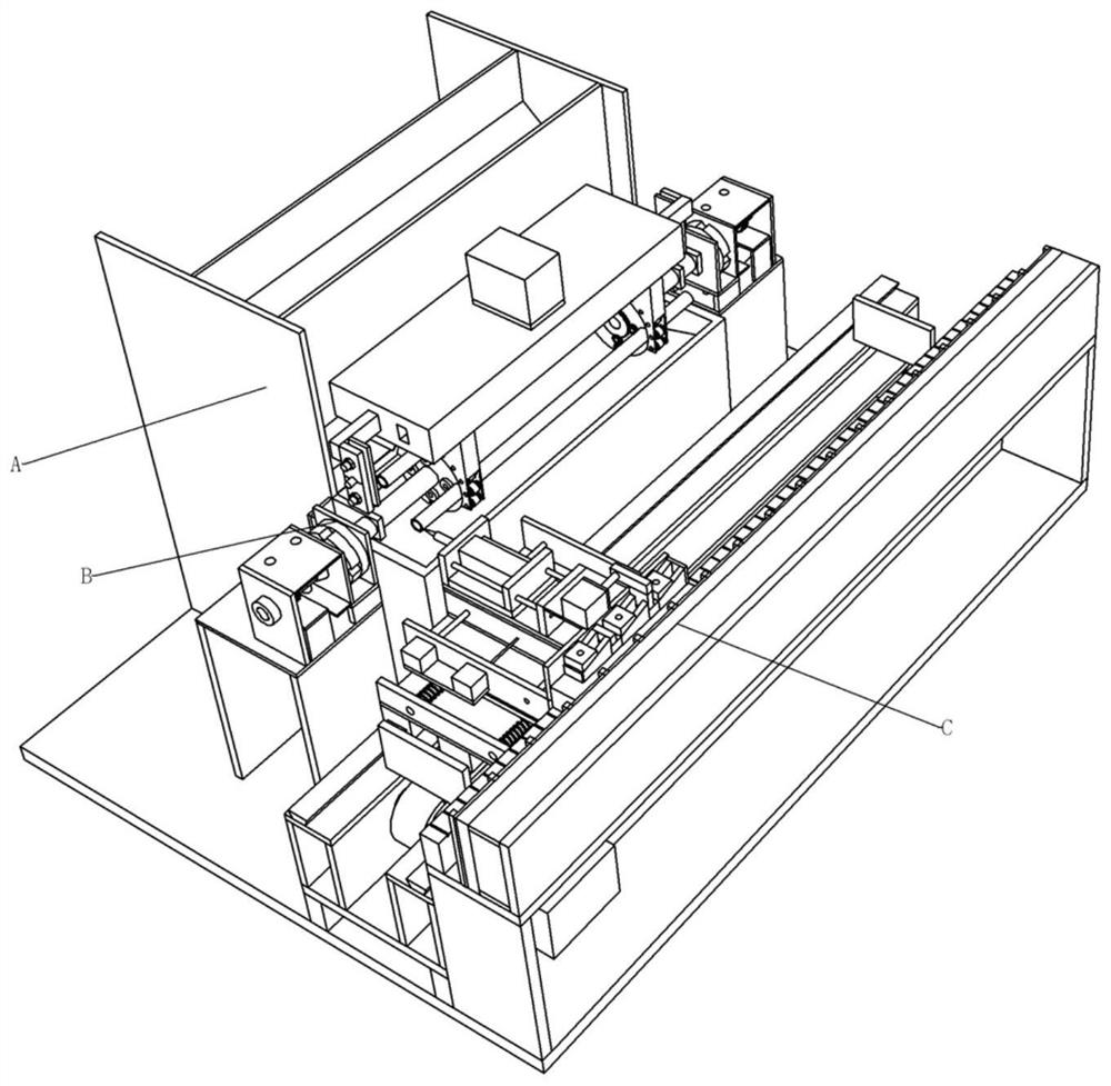
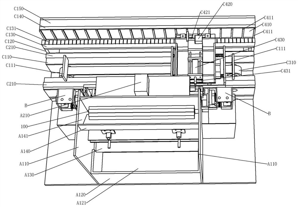
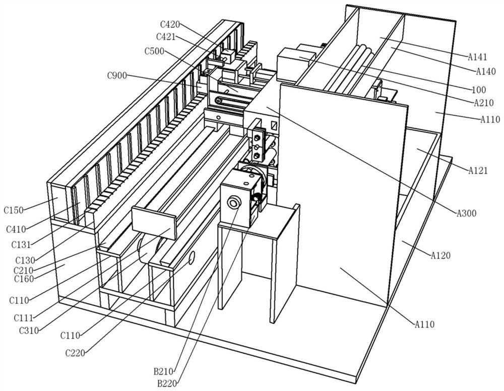
[0030] see Figure 1-Figure 33 , the fully automatic laser pipe cutting machine of the present embodiment, comprising:

[0031] Loading...


PUM


Abstract

The invention discloses a cutting module and a full-automatic laser pipe cutting machine. The full-automatic laser pipe cutting machine comprises a feeding module, a power module and the cutting module, wherein the feeding module is used for loading pipes to be cut into pipe grooves of a feeding wheel one by one, and then the feeding wheel rotates to enable the pipes to be cut to be sequentially subjected to the procedures of feeding, centering, clamping, section cutting and discharging; the power module is used for driving the pipes at the section cutting procedure to rotate so as to ensure that the whole circles of the pipes are cut off, and intermittently driving the feeding wheel to rotate so as to complete procedure switching; and the cutting module is used for cutting the pipes through laser emitted by a laser device, the pipes are relatively fixed in the axial direction, and laser cutting heads move in the axial direction of the pipes and positioning is carried out, so that accurate cutting of the pipes is completed. Automatic feeding can be achieved, and the five procedures of feeding, clamping, axial alignment, section cutting and discharging can be synchronously achieved,so that the production efficiency is improved by at least two times or above. In addition, the mode that the laser device moves while the pipes are fixed is adopted, and the full-automatic laser pipecutting machine can adapt to pipes with more lengths.

Description

technical field [0001] The invention relates to pipe cutting equipment, in particular to a fully automatic laser pipe cutting machine. Background technique [0002] In actual processing and manufacturing, since the pipes purchased are generally relatively long, they need to be cut into sections according to the design length. Considering the requirements for the flatness of the incision, a laser pipe cutting machine is generally selected. The current related equipment mainly adopts a small trailer to drag the long pipe, the laser does not move, and the small trailer drives the long pipe to move to the laser to adjust the length of the cut section. The small trailer is generally driven by a screw or a chain, and a round hole is opened inside to clamp the long pipe. A rotating wheel is installed in the round hole. The rotating wheel is pressed against the outer wall of the long pipe, and then the rotating wheel rotates to drive the long pipe to rotate in a circle. In order t...

Claims


Application Information

Patent Timeline
Patent Type & Authority Applications(China)
IPC IPC(8): B23K26/38B23K26/70
CPCB23K26/38B23K26/702B23K2101/06
Inventor 刘钟元
Owner CHONGQING WANCHONGSHAN INTELLIGENT TECH CO LTD
Why Eureka
Try Eureka