
A clutch pipe joint

A clutch tube and tube body technology, which is applied in the direction of pipes/pipe joints/fittings, hose connection devices, mechanical equipment, etc., can solve the problem of difficulty in adapting to hydraulic or pneumatic automatic clamps, increasing dragging pipes to exchange additional loads, and the size of pipe space Limitation and other issues, to achieve the effect of compact structure, small damping, and large internal passage

Active Publication Date: 2016-01-13
裕强智能机械(苏州)有限公司
View PDF6 Cites 1 Cited by
  • Summary
  • Abstract
  • Description
  • Claims
  • Application Information

AI Technical Summary

Problems solved by technology

When the workbench is replaced, the hose pipes are exchanged accordingly, which increases the additional load of dragging the pipe exchange. The space occupied by the number of pipes limits the number of workbenches. The length and erection of pipes are difficult to adapt to the large distance and multi-pallet flexible manufacturing unit The need for hydraulic or pneumatic automatic fixtures limits the connection of fluid pipes between any two objects such as the double exchange table of a CNC machine tool

Method used


Image

  • A clutch pipe joint

Examples


Embodiment Construction

[0014] The present invention will now be described in further detail in conjunction with the accompanying drawings and preferred embodiments. These drawings are all simplified schematic diagrams, which only illustrate the basic structure of the present invention in a schematic manner, so they only show the configurations related to the present invention.

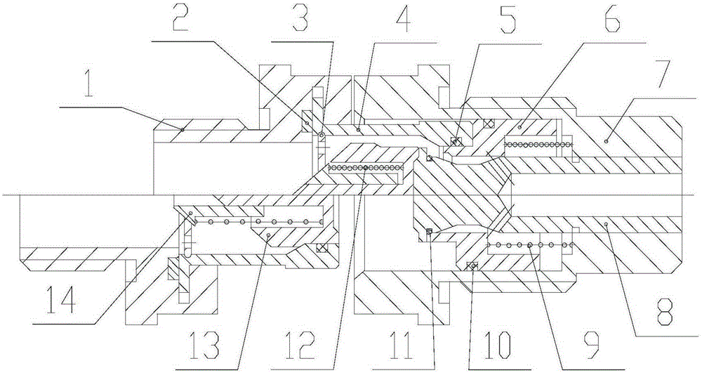
[0015] Such as figure 1 The clutch pipe joint shown is composed of two pipe bodies, one pipe body is fixedly connected with the fluid source object through threads, and the other pipe body is fixedly connected with the fluid supply object through threads, and the two objects are close to the two pipes When the bodies are further approached within a certain coaxial range, one body is inserted into the other body, and the passages inside the two bodies are automatically connected, and one object can provide pressure fluid to the other.

[0016] When the pipe body I1 moves close to the pipe body II7 and reaches a certain posit...


PUM


Abstract

The invention relates to a clutch pipe connector which comprises two pipe bodies. One pipe body is fixedly connected with a fluid source object through threads. The other pipe body is fixedly connected with a fluid feeding object through threads. When the two objects get more close to the two pipe bodies in a certain coaxial range, one pipe body is inserted into the other pipe body, channels in the two pipe bodies are communicated automatically, and one object can provide pressure fluid for the other object. When the two objects are separated from each other by a certain distance, the two pipe bodies are separated along with the objects, the fluid channels in the pipe bodies are sealed respectively, and the distance between the two separated objects is not limited. The clutch pipe connector is small in size, compact in structure, a fixing soft pipe does not need to be hung, the inner channels are large, damping is low, high-flow-speed pressure loss is small, an azimuth error compensation function is achieved, when the tow pipe bodies get close to be in a certain coaxiality position error range, the fluid channels can be reliably connected and disconnected, leakage cannot happen, and the clutch pipe connector can be used in any field.

Description

technical field [0001] The invention relates to a clutch pipe joint, in particular to a mechanical automatic clutch pipe joint. Background technique [0002] When hydraulic or pneumatic fixtures are installed on the exchange table of CNC machine tools, often each set of fixtures needs to be separately designed with a complete set of fixedly connected and suspended hose pipes. The more workbenches, the more pipes. When the workbench is replaced, the hose pipes are exchanged accordingly, which increases the additional load of dragging the pipe exchange. The space occupied by the number of pipes limits the number of workbenches. The length and erection of pipes are difficult to adapt to the large distance and multi-pallet flexible manufacturing unit The need for hydraulic or pneumatic automatic fixtures limits the connection of fluid pipes between any two objects such as the double exchange table of a CNC machine tool. Contents of the invention [0003] The technical problem...

Claims


Application Information

Patent Timeline
Patent Type & Authority Patents(China)
IPC IPC(8): F16L37/36F16L33/00
CPCF16L33/00F16L37/36
Inventor 周保牛张波虞文武周岳王涛
Owner 裕强智能机械(苏州)有限公司
Learn More