Synchronous rectification control system and method based on time domain multiplier

A technology of synchronous rectification and control system, which is applied in the field of synchronous rectification control based on time domain multiplier, synchronous rectification control system, and synchronous rectification control system based on time domain multiplier, can solve the limitation of synchronous rectification power MOS tube turn-on time, Switching power supply noise, frequency jitter and other problems

Active Publication Date: 2014-08-27
佛山市南海赛威科技技术有限公司
View PDF4 Cites 17 Cited by
  • Summary
  • Abstract
  • Description
  • Claims
  • Application Information

AI Technical Summary

Problems solved by technology

[0015] This control method must consider two factors that may cause damage. One is that the noise of the switching power supply is very large, which will cause certain fluctuations in the degaussing time of each cycle; the other is frequency jitter. In order to improve EMI, the switching power suppl

Method used


Image

  • Synchronous rectification control system and method based on time domain multiplier
  • Synchronous rectification control system and method based on time domain multiplier
  • Synchronous rectification control system and method based on time domain multiplier

Examples


Embodiment 1

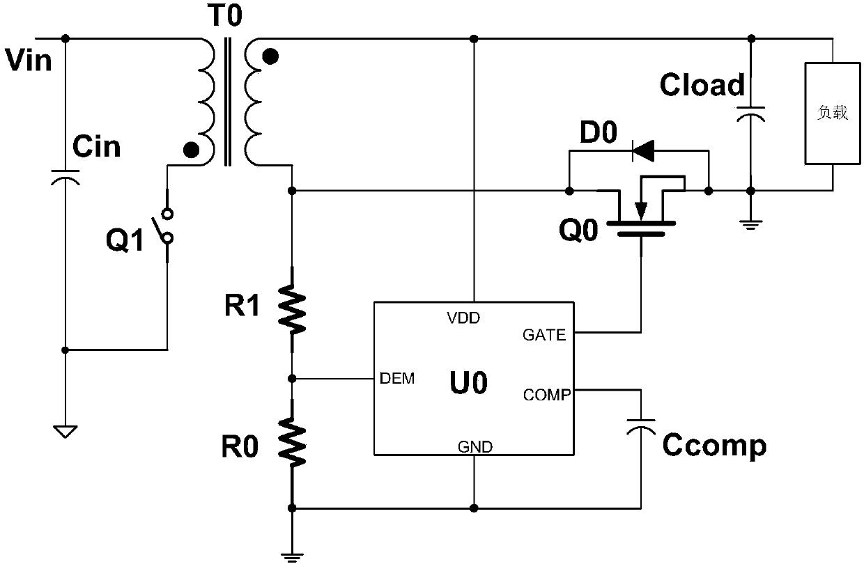
[0074] see figure 1 , the present invention discloses a novel synchronous rectification control system, figure 1 It is a specific embodiment proposed according to the present invention in the flyback system, and the idea and method of the present invention will be described below in conjunction with pictures.

[0075] see figure 1 , the synchronous rectification control application system based on the present invention includes: a synchronous rectification power MOS transistor Q0, a diode D0 connected in parallel with the synchronous rectification power MOS, an energy storage transformer T0, and a degaussing detection voltage dividing resistor R0 connected to the drain end of the synchronous rectification power MOS transistor and R1, the external loop integration capacitor Ccomp, and the synchronous rectification control module U0 based on the time domain multiplier.

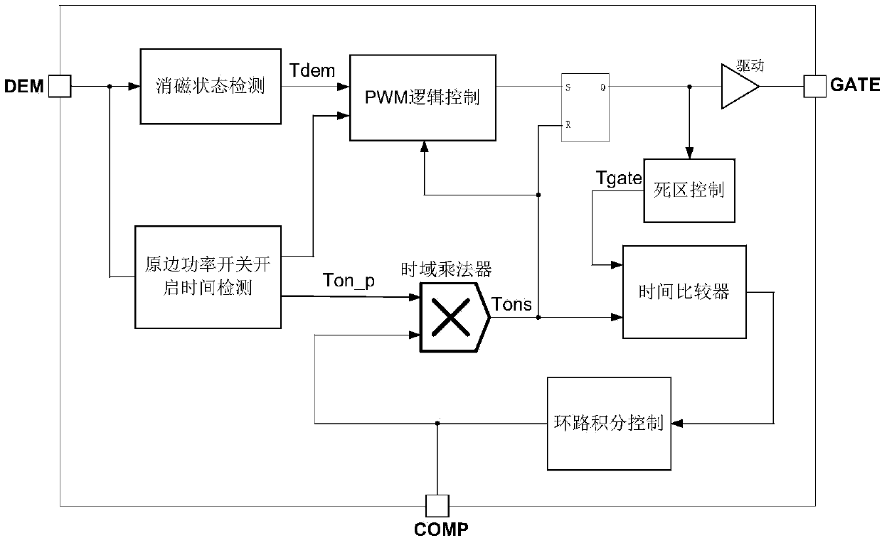
[0076] The internal modules of the control module U0 can be found in figure 2 . The synchronous rectific...

Embodiment 2

[0092] This embodiment discloses a control method of the synchronous rectification control system described in Embodiment 1, and the control method includes the following steps:

[0093] The degaussing state detection module detects the degaussing starting point and the degaussing duration Tdem of the transformer or inductor, and records the degaussing duration of the previous cycle as Tdem0;

[0094] The primary side power switch turn-on time detection module detects and determines the time point of opening and closing of the primary side power switch, and records the turn-on time of the primary side power switch in the previous cycle as Tons0;

[0095] The dead zone control module controls the synchronous rectification power MOS tube to leave a set dead zone between the shutdown and the end of degaussing;

[0096] The PWM control logic control module issues an open signal at the start point of degaussing by processing internal signals;

[0097] The RS flip-flop triggers the...


PUM


Abstract

The invention discloses a synchronous rectification control system and method based on a time domain multiplier. The control system comprises a degaussing detection state detection module, a primary side power switch turn-on time detection module, a time domain multiplier module, a dead zone control module, a PWM logic control module, an RS latch, a driving module, a time comparator module and a loop integral control module. The synchronous rectification control system and method based on the time domain multiplier not only can ensure safety of synchronous rectification control, but also can achieve the maximum synchronous rectification MOS transistor switch-on time in theory, thereby maximizing the efficiency of the synchronous rectification technology; compared with the existing control technology, the synchronous rectification control system and method have the obvious advantages and has the high practicability.

Description

technical field [0001] The invention belongs to the technical field of integrated circuit design, and relates to a synchronous rectification control system, in particular to a synchronous rectification control system based on a time domain multiplier; at the same time, the invention also relates to a synchronous rectification control method based on a time domain multiplier . Background technique [0002] With the rapid development of my country's economy, people's demand for electricity in production and life has increased, but the energy supply at home and abroad has not increased correspondingly, resulting in increasingly serious energy shortages. Electric energy is an important part of energy, and the requirements for the efficiency of electric energy use are becoming more and more stringent. At present, the power supply is mainly through high-voltage AC, generally in the range of 110V ~ 220V, while ordinary household appliances usually use DC power supply, so it is nec...

Claims


Application Information

Patent Timeline
IPC IPC(8): H02M7/217H02M1/08
Inventor 职春星林凯杨展悌叶俊
Owner 佛山市南海赛威科技技术有限公司
Why Eureka
Try Eureka