Method for manufacturing battery terminal plate

A manufacturing method and technology of battery terminals, applied to batteries, battery pack parts, battery boxes/coatings, etc., can solve the problems that the processed materials cannot be processed into a specified shape, the moving path of the processing device becomes longer, and processing cannot be performed.

Inactive Publication Date: 2014-08-27
姜泰仁 +1
View PDF2 Cites 4 Cited by
  • Summary
  • Abstract
  • Description
  • Claims
  • Application Information

AI Technical Summary

Problems solved by technology

[0013] On the other hand, in the method of manufacturing a battery terminal plate using an existing forging machine, after cutting the material to be processed continuously supplied in the form of a wire into a predetermined length, the cut material to be processed is transferred to a plurality of punching presses. Machine, while processing, so not only the moving path of the processed material is lengthened, but also the moving path of the processing device is lengthened, which has the problem of lowering productivity.
[0014] In addition, in the case of conventional forging, since it is processed in an unfolded manner, in the case of processing into an asymmetric shape, for example, in the case of processing to have a height difference in which one side is thick and the other side is thin , there is a problem that the processed material cannot be processed into a specified shape or cannot be processed according to the size

Method used


Image

  • Method for manufacturing battery terminal plate
  • Method for manufacturing battery terminal plate
  • Method for manufacturing battery terminal plate

Examples


Embodiment Construction

[0031] The invention is described below with reference to the presented drawings.

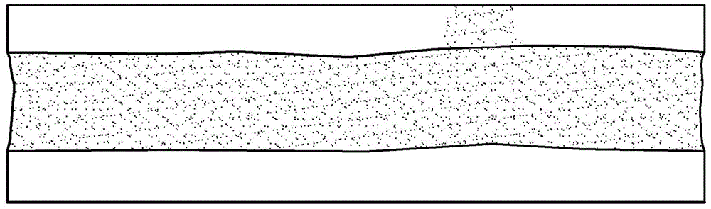
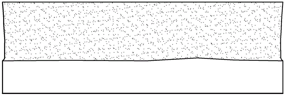
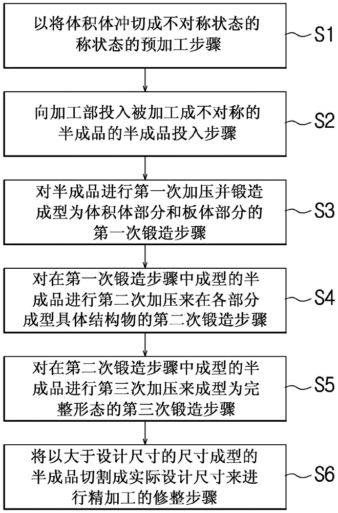
[0032] First of all, the present invention is as shown in the accompanying drawings image 3 As shown, it can be carried out according to the following steps, that is: the preprocessing step S1, the single processed material G in the form of a volume body is press-processed into the semi-finished product G-1 of an asymmetric shape for the first time through the punching device 110; the semi-finished product input step S2, the pick-up device 12 grasps the semi-finished product G-1 which is continuously supplied in the state of the first processing, and transfers it to the first processing part 130; the first forging step S3, the first punch 161 faces the above-mentioned The semi-finished product G-1 put into the first processing part 130 is pressurized to be forged for the first time and formed into a volume body part and a plate body part; the second forging step S4 is to perform the first punc...


PUM


Abstract

The present invention relates to a method for manufacturing a battery terminal plate and the manufacturing method is characterized by comprisng: a pre-processing step (S1) for primarily press-processing single objects (G) in the shape of a volume body to be processed into asymmetrical-shaped semi products (G-1) via a press cutting device (110); a semi product insertion step (S2) for conveying the semi products (G-1) which are continuously supplied in the primarily processed state to a first processing unir(130) by holding the same with a pickup device (120); a first forging step (S3) for primarily forging the semi products (G-1) which are inserted into the first processing unit(130) by asymmetrically pressing the same with a first punch (161); a second forging step (S4) for secondarily forging the semi products (G-1) which are positioned in the first processing unit(130) by asymmetrically pressing the same with a second punch (162) which performs a pressing operation in connection with the first punch (161) such that a pickup-holding member (G*) is configured to be held and conveyed; a third forging step (S5) for tertiarily forging the semi products (G-1) by pressing the same with relatively stronger pressure than that of the second forging step with a third punch (163) when the the secondarily forged semi products (G-1) are positioned in the first processing unit(130) or when the secondarily forged semi products (G-1) are conveyed from the first processing unit(130) to a second processing unit(140), such that break lines on the outside of the semi products (G-1) are pressed and filled; and a trimming step (S6) for punching the tertiarily forged semi products (G-1) so as to remove the pickup-holding member (G*1) with a cutting-trimming unit (170) which performs lifting and pressing operations when the tertiarily forged semi products (G-1) are positioned in the second processing unit (140) or when the tertiarily forged semi products (G-1) are conveyed to a third processing unit(150), and simultaneously cutting the outside rim portion thereof according to a design dimension so as to cut the same as finished products (G-2).

Description

technical field [0001] The present invention relates to a manufacturing method of a battery terminal board, and in more detail, relates to a manufacturing method of a finished battery terminal board by processing a workpiece, such as a battery terminal board for an electric vehicle with an asymmetric basic shape, step by step. Background technique [0002] With the tightening of environmental restrictions, the future competitiveness of the automobile market depends on the research and development of environmentally friendly vehicles. Eco-friendly cars that started to emerge in the 1990s were first commercialized and developed under the name of hybrid electric vehicles (Hybrid car). [0003] In particular, due to high oil prices and environmental problems recently, interest in environmentally friendly vehicles has increased day by day. Therefore, the above-mentioned hybrid electric vehicle (HEV, Hybrid Electric Vehicle) market growth rate is as high as 60% per year. It is pre...

Claims


Application Information

Patent Timeline
Patent Type & Authority Applications(China)
IPC IPC(8): H01M2/30H01M2/10H01M50/552
CPCH01M2220/20Y10T29/49108H01M2/342H01M2/30H01M50/597H01M50/552Y02E60/10H01M50/543
Inventor 姜泰仁金龙洙
Owner 姜泰仁
Why Eureka
Try Eureka