Patient warming device with patient access

a patient-access, patient-friendly technology, applied in the direction of therapeutic heating, contraceptive devices, therapeutic cooling, etc., can solve the problems of patient's perioperative hypothermia, systemic vasodilation, and body's natural thermoregulatory mechanisms may be affected,

Active Publication Date: 2016-09-13
SUNMED GRP HLDG LLC
View PDF53 Cites 5 Cited by
  • Summary
  • Abstract
  • Description
  • Claims
  • Application Information

AI Technical Summary

Problems solved by technology

As a result, the body's natural thermoregulatory mechanisms may be affected and systemic vasodilation may occur.
As a result, the patient is at risk of perioperative hypothermia.
Medical complications may result from perioperative hypothermia and may include peri-operative and post-operative complications, including for example, increased wound infection rates, metabolic acidosis, respiratory distress, cardiovascular effects, surgical bleeding, and increased risk of mortality.
These warming devices generally cover a large portion of the body, restricting access to the patient in covered areas.
Removal and repositioning of the device not only increases the time required for the surgical procedure, but may also significantly reduce heat transfer to the patient during that time.
Moreover, control systems for forced air convective devices tend to generate loud noise that may distract or interfere with communication between surgeons and medical personnel in an operating room.
Active warming devices also tend to cause stippling on patients' skin.
Stippling may cause pain in geriatric or elderly patients, pediatric or very young patients, or patients with sensitive skin.
Stippling is also unsightly, and may evoke unnecessary concern from a patient and from friends and family members who observe the stippling on the patient's skin.
DVT prevention devices may use negative pressure, or vacuum pressure, to apply compression, which requires a seal around the patient's extremity and does not allow for access to the underlying surface of the patient.
Applying negative pressure, or vacuum pressure, for DVT prevention also tends to increase stippling.

Method used


Image

  • Patient warming device with patient access
  • Patient warming device with patient access
  • Patient warming device with patient access

Examples


Embodiment Construction

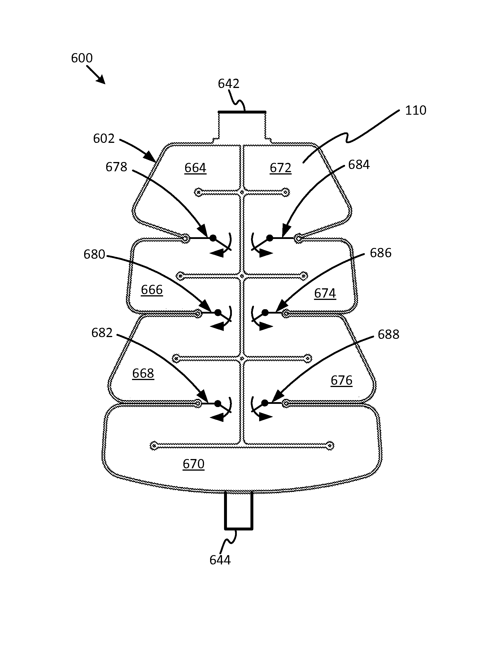
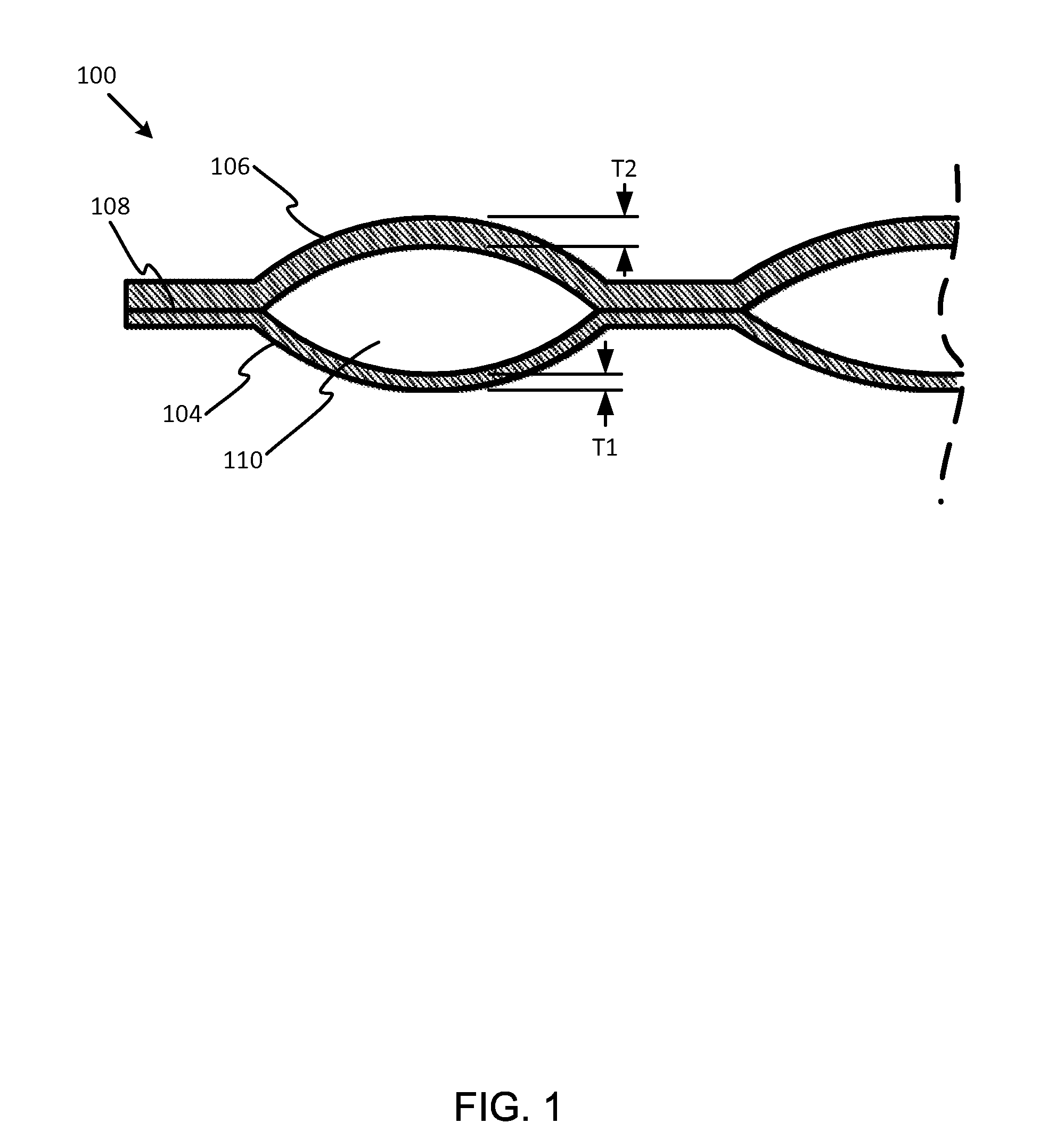
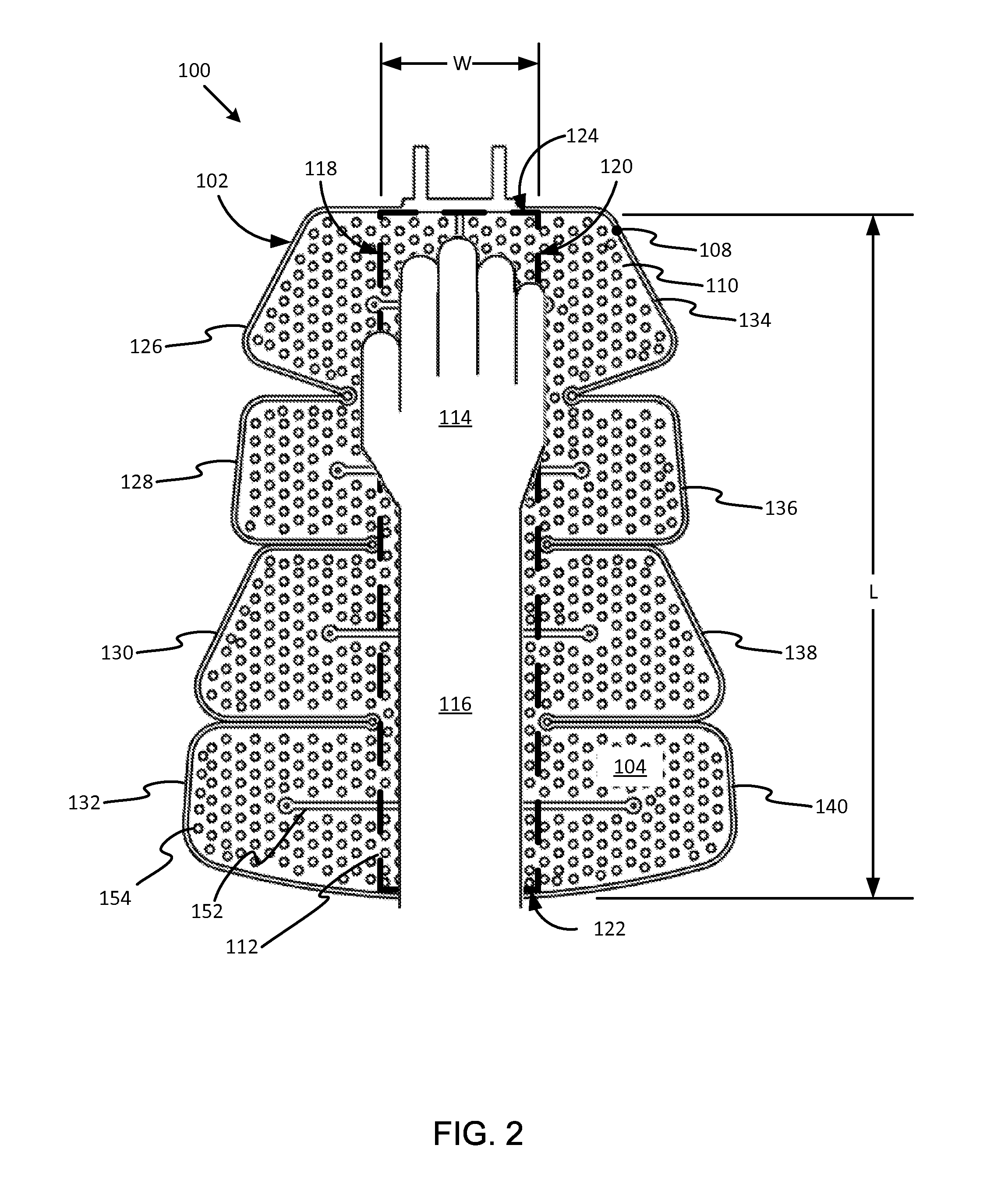
[0028]Commonly owned U.S. application Ser. Nos. 13 / 801,270 and 13 / 801,334 entitled, respectively, “Compressive Patient Warming Device” and “Patient Warming and Deep Vein Thrombosis Prevention System,” are being filed concurrently herewith, and each is incorporated herein by reference in its entirety. Various embodiments are described below with reference to the drawings in which like elements generally are referred to by like numerals. The relationship and functioning of the various elements of the embodiments may better be understood by reference to the following detailed description. However, embodiments are not limited to those illustrated in the drawings. It should be understood that the drawings are not necessarily to scale, and in certain instances details may have been omitted that are not necessary for an understanding of embodiments disclosed herein, such as—for example —conventional fabrication and assembly. The invention is defined by the claims, may be embodied in many d...


PUM


Abstract

A patient warming device with patient access for maintaining normothermia and / or treating hypothermia is provided. The device includes a first compliant layer and a second compliant layer sealed together around an outer border to contain a liquid between the two layers and to form a wrap that surrounds and conforms to a body portion of a patient. A plurality of flaps extends from opposite sides of a generally longitudinal central portion of the wrap, such that one or more flaps from the opposite sides fasten to each other to surround the body portion. The flaps are openable during functional use to provide access to an underlying patient body surface. A continuous fluid flow path extends between the first compliant layer and the second compliant layer between a fluid inlet and a fluid outlet to carry liquid and deliver heat through the wrap.

Description

TECHNICAL FIELD[0001]Embodiments disclosed in the present application relate generally to patient warming devices embodied as wraps for maintaining normothermia and / or treating hypothermia.BACKGROUND[0002]During surgical procedures, patients may be placed under anesthesia. As a result, the body's natural thermoregulatory mechanisms may be affected and systemic vasodilation may occur. Systemic dilation counteracts the body's natural heat retention mechanism and allows body heat to flow down a concentration gradient to the extremities, where heat is lost to the environment. As a result, the patient is at risk of perioperative hypothermia. Medical complications may result from perioperative hypothermia and may include peri-operative and post-operative complications, including for example, increased wound infection rates, metabolic acidosis, respiratory distress, cardiovascular effects, surgical bleeding, and increased risk of mortality. Therefore, a need exists for patient warming devi...

Claims


Application Information

Patent Timeline
Patent Type & Authority Patents(United States)
IPC IPC(8): A61F7/02A61F7/00
CPCA61F7/02A61F2007/0029A61F2007/0031A61F2007/0034A61F2007/0036A61F2007/0037A61F2007/0039A61F2007/0043A61F2007/0045A61F2007/0054A61F2007/0215A61F2007/0217A61F2007/0219A61F2007/0228A61F2007/0231A61F2007/0268A61F2007/0273A61F2007/0274A61F2007/0288A61F2007/0041A61F2007/0226
Inventor VARGA, CHRISTOPHER M.MCMAHON, MICHAELDILLINGHAM, THOMASCHAN, JAMESSCHMALTZ, TODDRAJENDRAN, KARTHIKEYAN
Owner SUNMED GRP HLDG LLC
Why Eureka
Try Eureka