Microfluid drive unit based on infiltration

A technology of driving device and osmosis, which is applied in the field of microfluidic driving device based on osmosis, can solve the problems of huge micropump driver, complex processing technology, difficult to replace liquid flow, etc., and achieve low cost, simple overall structure and high liquid flow rate. stable effect

Inactive Publication Date: 2008-09-03
NORTHEASTERN UNIV
View PDF0 Cites 5 Cited by
  • Summary
  • Abstract
  • Description
  • Claims
  • Application Information

AI Technical Summary

Problems solved by technology

However, these micropumps often require bulky drivers, which is inconvenient to use
Other types of non-mechanical micropumps also have shortcomings: for example, the pump pressure of a gravity pump is affected by the height of the space and the viscosity of the liquid flow, which is suitable for continuous delivery and is not easy to replace the liquid flow; the running time of the capillary action micropump is affected by the liquid storage capacity of the capillary channel. If the operation time is to be extended, the processing technology will become complicated; while the evaporation force driven micro-pump is not only limited by the water absorption of the water-absorbing agent, but also by the environmental humidity and other conditions.

Method used


Image

  • Microfluid drive unit based on infiltration
  • Microfluid drive unit based on infiltration
  • Microfluid drive unit based on infiltration

Examples


example 1

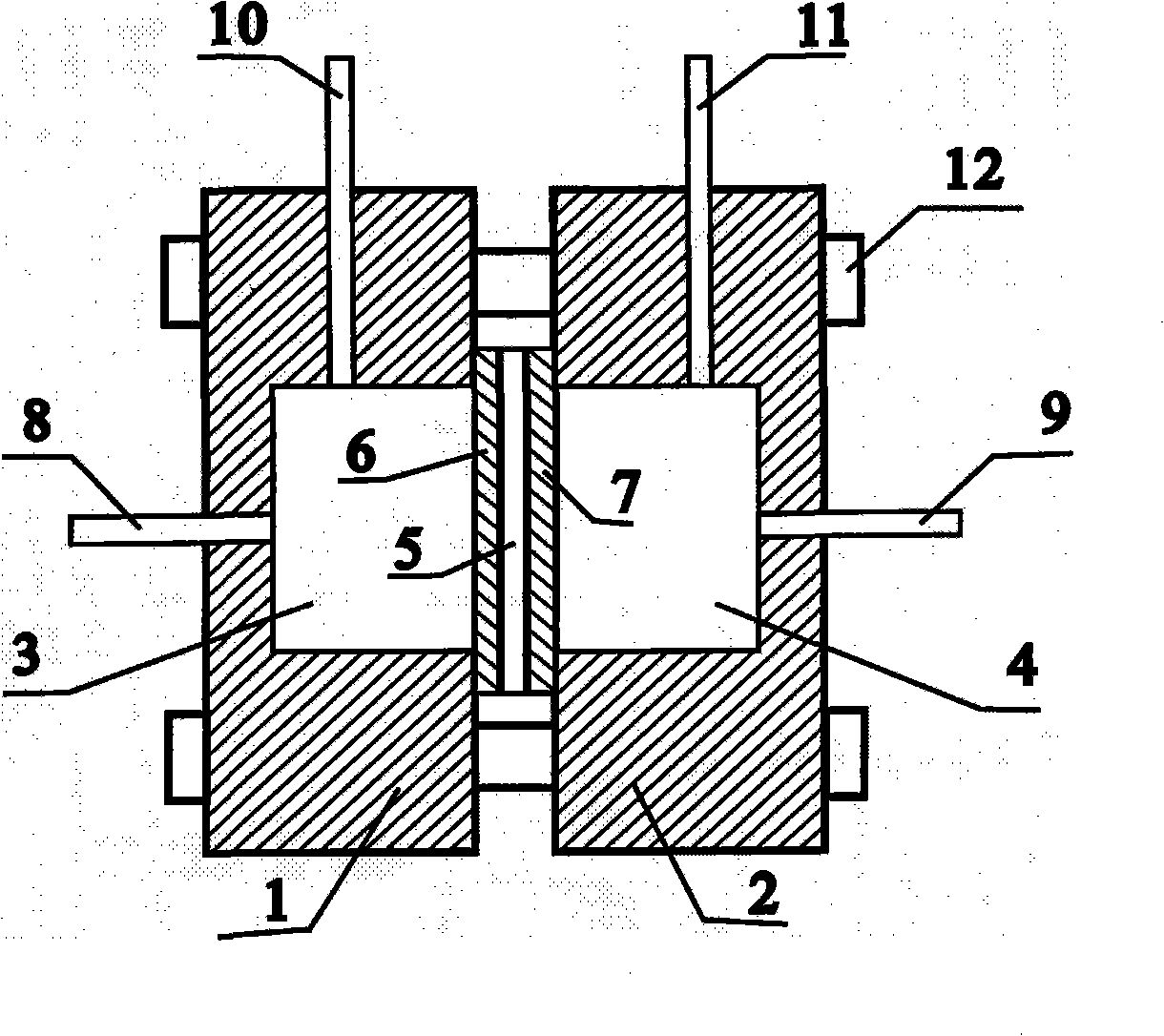
[0016] Example 1: The structure of the microfluid drive device of the present invention is as attached figure 1 As shown, there is a first pool body 1 with a first liquid storage tank 3 and a second pool body 2 with a second liquid storage tank 4, all of which are made of polymethyl methacrylate (purchased in the market), The volumes of the first liquid storage tank 3 and the second liquid storage tank 4 are equal, and on the inner side walls corresponding to each other of the first tank body 1 and the second tank body 2, there is a The opening of the liquid storage pool 4 communicates with the cavity. There is an inlet 8 of the first liquid storage pool 3 on the outer wall of the first pool body 1, and an outlet of the second liquid storage pool 4 on the outer wall of the second pool body 2. 9. There is an exhaust port 10 of the first liquid storage tank 3 on the first pool body 1, and an exhaust port 11 of the second liquid storage tank on the second pool body 2. The semi-p...

example 2

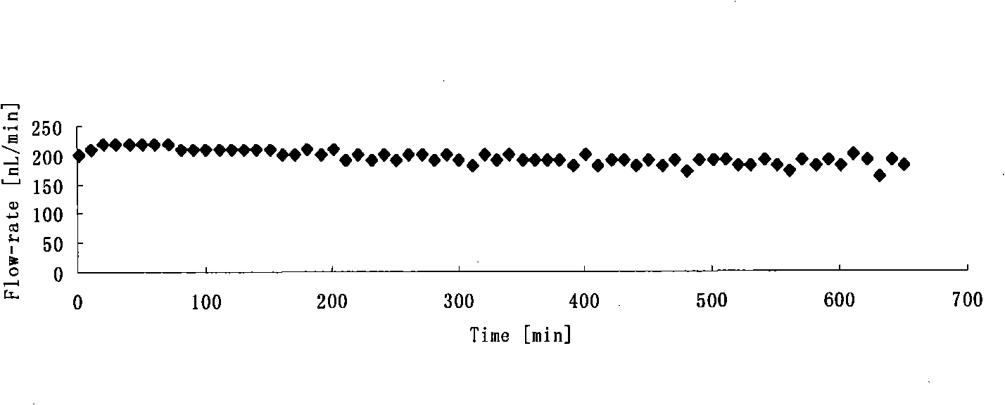
[0018] Example 2: The device structure and operation steps are the same as Example 1, the difference is that the osmotic driving reagent is selected as 40 mg mL -1 Polyvinylpyrrolidone (PVPK17, molecular weight 8000, pharmaceutical grade, purchased from Henan Boai Xinkaiyuan Pharmaceutical Co., Ltd.) solution, the test result is that the average flow rate in 650min is 195nLmi n- 1, RSD is 7.0% (n=66), such as image 3 .

example 3

[0019] Example 3: The device structure and operation steps are the same as Example 1, the difference is that the osmotic driving reagent is selected as 200 mg mL -1 The PVPK25 (molecular weight 34000, pharmaceutical grade, purchased from Henan Boai Xinkaiyuan Pharmaceutical Co., Ltd.) achieved a record of continuous work within 294 hours. Flow rate from 650nL min -1 down to 120nL min -1 .


PUM


Abstract

The invention relates to a microflow driving device based on osmosis. Two floor plates sandwiched by a semipermeable membrane and installed between two tank bodies of aqua storage tanks with constant volume body and connected by bolt and nut. Two tank bodies all have one vent of aqua storage tank. One inlet or outlet of one aqua storage tank is provided on the outer sidewalls of the two tank bodies and one opening communicated with the cavity for storing liquid is respectively on the corresponding point of the inner wall of the two tank bodies. The minipores are all dispersed on the two floor plates, wherein the aperture diameter of minipore is 0.4-2mm and the cutoff molecular weight of semipermeable membrane is less than the molecular weight of infiltration driving agent. On running, the aqua storage tank is filled with deionized water and another aqua storage tank is filled with infiltration driving agent, therefore the gas of the two aqua storage tanks are removed and the flow speed and stability of micropump can be measured after closing the vent. The whole structure is simple and the cost is low. The microflow driving device is convenient for carrying without external resource and continuously serves for many days and the liquid flow is stable, adjustable without pulse.

Description

technical field [0001] The invention belongs to a microfluid drive device, in particular to a microfluid drive device based on osmosis. Background technique [0002] In the microfluidic analysis system, the microfluidic chip is characterized by a network of microchannels in various configurations. It completes the separation and analysis function of the chip system by manipulating the fluid in the channel. The microfluidic drive technology compatible with microchannels is the premise and basis for realizing microfluidic control. Especially based on technologies such as micro-electromechanical system (MEMS), microfluidic drive technology has developed rapidly in the past ten years, and various micropumps emerge in endlessly. According to whether the drive system has movable mechanical parts, the microfluidic drive system can be divided into micro-drive systems with movable mechanical drive parts and micro-drive systems without movable mechanical drive parts, referred to as m...

Claims


Application Information

Patent Timeline
Patent Type & Authority Applications(China)
IPC IPC(8): G01N35/00
Inventor 徐章润杨春光
Owner NORTHEASTERN UNIV
Why Eureka
Try Eureka