Fixed scroll of scroll compressor

A scroll compressor and scroll technology, applied in mechanical equipment, machines/engines, liquid fuel engines, etc., can solve the problems of reducing the volumetric efficiency of the compressor and the overall performance of the compressor

Inactive Publication Date: 2006-10-04
LG ELECTRONICS INC
View PDF0 Cites 5 Cited by
  • Summary
  • Abstract
  • Description
  • Claims
  • Application Information

AI Technical Summary

Problems solved by technology

This significantly reduces the volumetric efficiency of the compressor, resulting in a decrease in overall compressor performance

Method used


Image

  • Fixed scroll of scroll compressor
  • Fixed scroll of scroll compressor
  • Fixed scroll of scroll compressor

Examples


Embodiment Construction

[0023] Now, preferred embodiments of the present invention will be described with reference to the accompanying drawings.

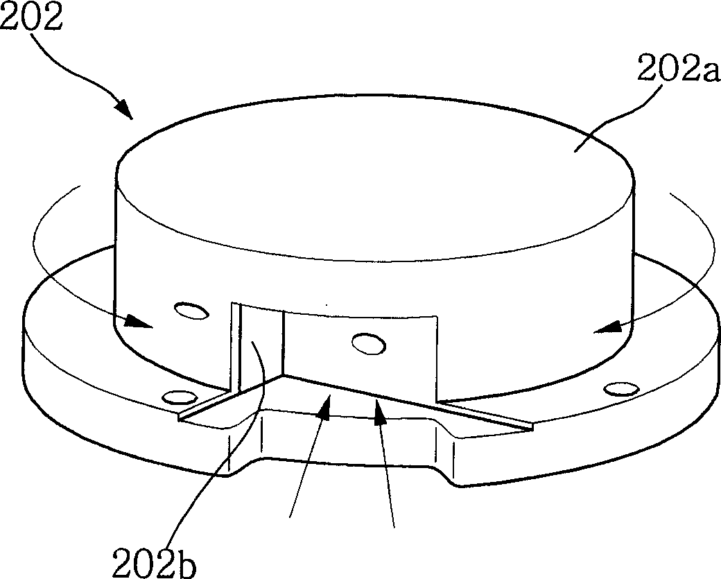
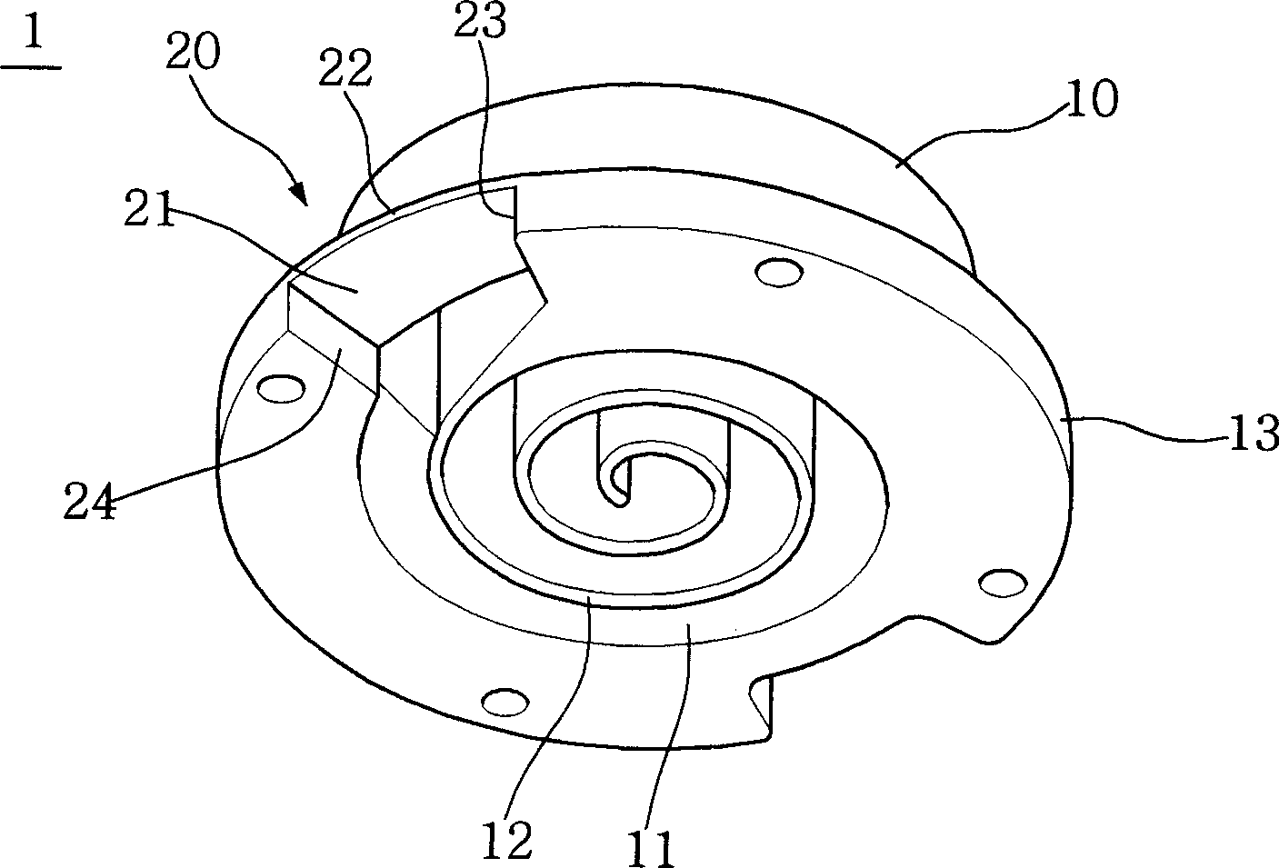
[0024] image 3 It is a bottom perspective view of the fixed scroll of the present invention. Figure 4 for image 3 A perspective view of the fixed scroll, which is connected to the main frame.

[0025] Such as image 3 and Figure 4 As shown, the fixed scroll 1 of the scroll compressor includes: a scroll body 10, which is arranged on the upper surface of the main frame 2 and defines a compression cavity 11 therein; and a cut-off suction portion 20, which forms a On the scroll body 10 to introduce the gaseous refrigerant into the compression chamber 11 .

[0026] The scroll body 10 has: an involute wrap body 12 defining a compression chamber 11 therein; and a mounting flange 13 formed around a lower end of the scroll body 10 to be mounted on the upper surface of the main frame 2 .

[0027] The cut-off suction portion 20 is used to guide only the su...


PUM


Abstract

Disclosed herein is a scroll compressor, and more particularly, a fixed scroll of the scroll compressor which can allow part of gaseous refrigerant to be smoothly introduced into a compression chamber while preventing introduction of the remaining gaseous refrigerant that is heated in the compressor. The fixed scroll includes a scroll body having an involuted wrap to define a compression chamber therein and provided, around a lower end thereof, with a mounting flange to be arranged on an upper surface of a main frame, and an interceptive suction portion configured to guide part of the gaseous refrigerant, that is directed upward along the main frame, into the compression chamber while preventing introduction of the remaining gaseous refrigerant that is circulated around the scroll body.

Description

technical field [0001] The present invention relates to a scroll compressor, in particular to a fixed scroll of the scroll compressor. The fixed scroll can make the gaseous refrigerant introduced into the compressor casing through the suction pipe directly into the compressor without being heated. cavity. Background technique [0002] figure 1 It is a longitudinal sectional view of important components of a traditional scroll compressor. figure 2 for figure 1 A perspective view of the fixed scroll in . [0003] Such as figure 1 and figure 2 The arrows shown in represent the flow direction of the sucked gaseous refrigerant. [0004] Such as figure 1 and figure 2 As shown in , the traditional scroll compressor includes: a casing 100, which defines a sealed space and is provided with a suction pipe 101 and a discharge pipe 102; a compression assembly 200, which is arranged on the upper part of the casing 100 and is suitable for compressing gaseous refrigerant and a ...

Claims


Application Information

Patent Timeline
Patent Type & Authority Applications(China)
IPC IPC(8): F04C29/00F04C18/02
CPCF04C2250/101F04C23/008F04C18/0253F04C18/02
Inventor 南重元俞炳吉
Owner LG ELECTRONICS INC
Why Eureka
Try Eureka