Gas combustion type driving tool

A technology for driving tools and gases, applied in nailing tools, manufacturing tools, etc., can solve the problems of reduced combustion energy, reduced combustion chamber volume, difficult ignition, etc., and achieves the effect of increasing striking force and improving combustion efficiency.

Inactive Publication Date: 2009-04-01
MAX CO LTD
View PDF2 Cites 4 Cited by
  • Summary
  • Abstract
  • Description
  • Claims
  • Application Information

AI Technical Summary

Problems solved by technology

[0006] But, there is following problem in the structure of above-mentioned Fig. 4 (a): because the upper wall 30 of combustion chamber 6 is formed higher, so the volume of combustion chamber as a whole increases, has improved combustion energy; When approaching the spark plug 20, the speed when passing in front of the spark plug 20 is fast, so it is difficult to ignite
[0007] In addition, in the structure of Fig. 4 (b), there is the following problem: when the gas flow a of the mixed gas passes through the front of the spark plug 20, a vortex is generated to slow down the flow velocity. Therefore, although the ignition can be performed more reliably, the upper wall of the combustion chamber 30 becomes lower, so the overall volume of the combustion chamber decreases, and the combustion energy decreases

Method used


Image

  • Gas combustion type driving tool
  • Gas combustion type driving tool
  • Gas combustion type driving tool

Examples


Embodiment Construction

[0033] Hereinafter, typical embodiments of the present invention will be described with reference to the drawings.

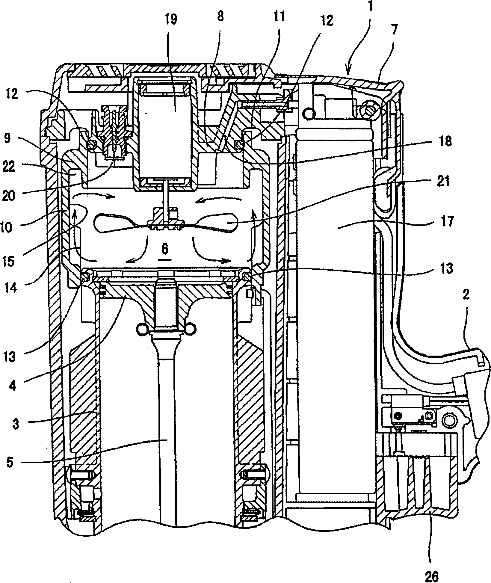
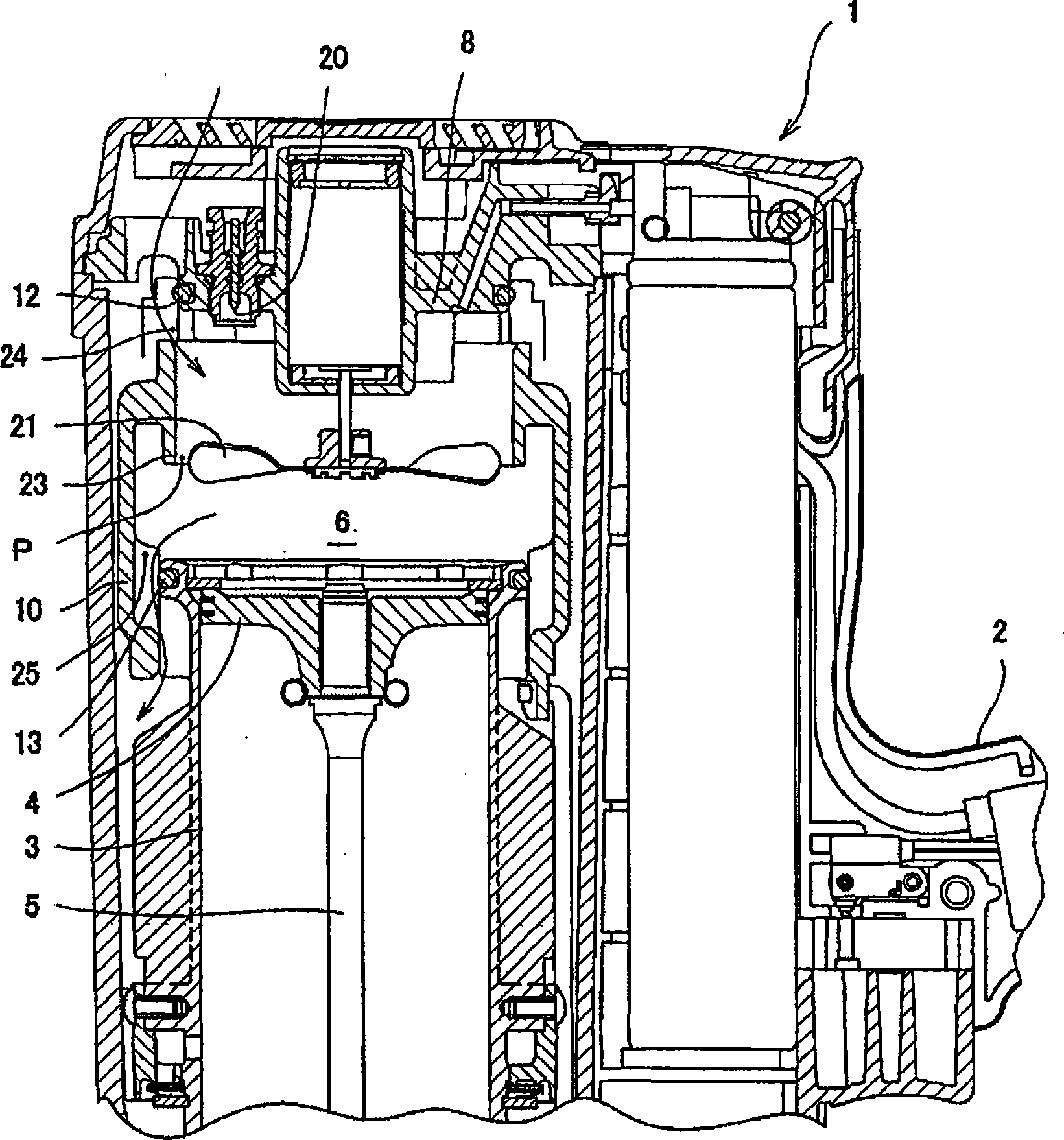
[0034] figure 1 and figure 2 In , reference numeral 1 denotes a tool body of a gas combustion driving tool (nail driver). The tool main body 1 is connected with a handle 2 and a staple cartridge (not shown), and is provided with a striking piston-cylinder mechanism inside. Below the tool main body 1, a head (not shown) for driving nails is provided.

[0035] In the striking piston-cylinder mechanism, a striking piston 4 is slidably accommodated in a striking cylinder 3 , and a driver 5 is integrally joined below the striking piston 4 .

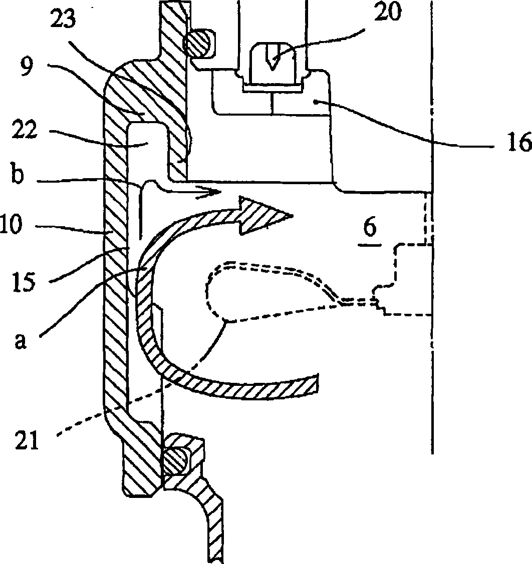
[0036] Next, form the combustion chamber 6 in an openable and closable manner on the top of the striking cylinder 3 . The combustion chamber 6 is formed by the upper end of the above-mentioned striking piston 4 and the movable sleeve 10, wherein the movable sleeve 10 is disposed between the striking cylinder 3 and the cylin...


PUM


Abstract

An enclosed combustion chamber (6) is formed by moving a movable sleeve (10) provided at a hammering cylinder (3) up and down thereby butting the movable sleeve (10) against a cylinder head (8) above the hammering cylinder (3). Flammable gas and air are stirred in the combustion chamber (6) by means of a rotary fan (21) to produce mixture gas which is then ignited by means of an ignition plug (20) and combusted explosively. High pressure combustion gas acts on a hammering piston (4) to drive the piston impulsively, and a driver (5) coupled to the lower surface of the hammering piston (4) hammers out a stud. The upper wall surface on the outside of the combustion chamber (6) is located remotely from the ignition plug (20) in order to decrease the current velocity of the mixture gas passing trough the upper wall surface sufficiently enough to cause no trouble in ignition when the gas reaches the ignition plug (20). A groove (22) opening to the combustion chamber (6) is formed in the upper wall surface.

Description

technical field [0001] The present invention relates to a gas combustion type driving tool that provides power through combustion and drives fasteners such as nails, and more particularly relates to a combustion type driving tool that improves the combustion chamber of the gas combustion type driving tool. Background technique [0002] In the gas combustion type driving tool, a fan is used to mix and stir combustible gas and air in the combustion chamber to obtain a mixed gas, ignite the mixed gas to detonate, and use the gas pressure of the combustion gas to drive the impact Piston (with reference to JP 2001-162560). [0003] However, combustible gas and air are supplied from the upper part of the combustion chamber, and are stirred and mixed by a fan installed in the center of the combustion chamber. At this time, the mixed gas is first blown downward by the fan. Therefore, after falling to the bottom of the combustion chamber and then diffusing to the outside, it rises a...

Claims


Application Information

Patent Timeline
Patent Type & Authority Applications(China)
IPC IPC(8): B25C1/08
CPCB25C1/08B25C1/18
Inventor 田村纯一村山胜彦竹村元小西正和
Owner MAX CO LTD
Why Eureka
Try Eureka