Lubricating device for lathe machining

A lubricating device and lathe processing technology, applied in metal processing equipment, metal processing mechanical parts, manufacturing tools, etc., can solve the problem of incorrect oil supply and collection amount of the oil tank, slow collection of lubricating oil, affecting the practicability and effect of machine tool processing, etc. problems, to achieve the effect of ensuring reuse efficiency, reducing the difference between oil supply and oil collection, and ensuring practicability and efficiency

Inactive Publication Date: 2017-12-01
周晓红
View PDF5 Cites 4 Cited by
  • Summary
  • Abstract
  • Description
  • Claims
  • Application Information

AI Technical Summary

Problems solved by technology

[0005] Aiming at the deficiencies of the prior art, the present invention provides a lubricating device for lathe processing, which has the advantages of high-efficiency lubrication, ensures long-term supply of lubrication, etc., and solves the problems caused by the accumulation of impurities in common machine tool lubricating devices. It makes the collection of lubricating oil slower, and it is prone to the problem that the amount of oil supplied by the oil tank is not equal to the amount collected, which effectively affects the practicability and effect of machine tool processing.

Method used


Image

  • Lubricating device for lathe machining
  • Lubricating device for lathe machining
  • Lubricating device for lathe machining

Examples


Embodiment Construction

[0028] The following will clearly and completely describe the technical solutions in the embodiments of the present invention with reference to the accompanying drawings in the embodiments of the present invention. Obviously, the described embodiments are only some, not all, embodiments of the present invention. Based on the embodiments of the present invention, all other embodiments obtained by persons of ordinary skill in the art without making creative efforts belong to the protection scope of the present invention.

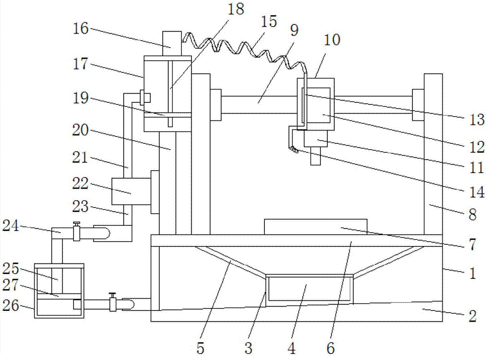
[0029] see Figure 1-3, a lubricating device for lathe processing, comprising a machine table (1), the bottom end of the inner cavity of the machine table (1) is fixedly installed with a built-in plate (2), and the inclination angle of the built-in plate (2) is fifteen degrees, And the lower end of the built-in plate (2) is close to the settling tank (26), and the width of the built-in plate (2) is greater than the width of the fixed frame (3), which ensures t...


PUM


Abstract

The invention discloses a lubricating device for lathe machining. The lubricating device for lathe machining comprises a machine table, wherein an internal plate is fixedly mounted at the bottom end of a cavity of the machine table; a fixed rack is fixedly mounted in the middle of the top end of the internal plate; an impurity collecting barrel is movably inserted in the fixed rack; side surfaces of the fixed rack are fixedly connected with sloping plates; the top ends of the sloping plates are fixedly connected with the bottom end of a supporting table; the supporting table is fixedly mounted at the top end of the machine table; and a machining table is fixedly mounted in the middle of the top end of the supporting table. According to the lubricating device for lathe machining, two precipitating tanks are matched with two flow distributing devices, collected lubricating oil is precipitated, tiny impurities which are doped in the lubricating oil are precipitated, by independent control of the other flow distributing device, the precipitated lubricating oil is guided out and used, precipitation is implemented by the two precipitating tanks alternately, therefore, the content of the impurities in the lubricating oil is greatly reduced, the purity of reused lubricating oil is improved, and the lubricating effect and long-time supply efficiency and effect are ensured.

Description

technical field [0001] The invention relates to the technical field of lubricating equipment, in particular to a lubricating device for lathe processing. Background technique [0002] Machine tool processing refers to the processing of raw materials with machine tools. The cutting process of the machine tool is realized by the relative motion between the tool and the workpiece. Its motion can be divided into surface forming motion and auxiliary motion. The processing accuracy includes the dimensional accuracy, shape accuracy, position accuracy and surface quality of the processed workpiece. and the precision retention of the machine tool, the production efficiency involves cutting processing time and auxiliary time, as well as the degree of automation and work reliability of the machine tool. On the one hand, these indicators depend on the static characteristics of the machine tool, such as static geometric accuracy and rigidity; The dynamic characteristics of the machine t...

Claims


Application Information

Patent Timeline
Patent Type & Authority Applications(China)
IPC IPC(8): B23Q11/10
CPCB23Q11/10B23Q11/1069Y02P70/10
Inventor 周晓红袁爱国吴峰
Owner 周晓红
Why Eureka
Try Eureka