Composite light guiding film module

A technology of light guide film and light, which is applied in the direction of light guide, optics, optical components, etc., and can solve the problems of high cost, light coupling into the film, light source into the film, etc.

Active Publication Date: 2009-07-01
IND TECH RES INST
View PDF0 Cites 4 Cited by
  • Summary
  • Abstract
  • Description
  • Claims
  • Application Information

AI Technical Summary

Problems solved by technology

[0002] Generally, small and medium-sized backlights, including mobile phones, PDAs, digital cameras, etc., mainly use side-light light-guiding backlight modules. Because small sizes pursue lightness, thinness, shortness, and even flexibility, thinning is a trend in product design. Backlights The source group is also constantly reducing its thickness. Ultra-thin light guide film is the main focus of technological development in various countries. There are many low-efficiency or ineffective light guide film products on the market, which only provide light diffusion, reflection or partial light coupling. In addition, limited by the value of the product, how to manufacture an ultra-thin light guide film with a film thickness of less than 300um in a simple way, the first thing to solve is how to effectively guide light into the film. In the thin diaphragm, the traditional light guide thick plate has a large cross-section, so it can be introduced by side light. The light source is parallel to the direction of the diaphragm, and the light will naturally couple into the diaphragm through the interface and transmit in the diaphragm. On the light source, the light pattern of the beam emitted by the CCFL cold cathode tube is relatively divergent, and the light pattern of the LED beam is more concentrated at 0 degrees, so the light guide plate used by the LED can be thinner, but when the beam size exceeds the thickness of the diaphragm, it cannot be directly Coupling LED light into the diaphragm can only be handled by complex and costly methods such as forced light coupling and focusing, and it is difficult to achieve an ultra-thin light guide diaphragm with high quality and low price

Method used


Image

  • Composite light guiding film module
  • Composite light guiding film module
  • Composite light guiding film module

Examples


Embodiment Construction

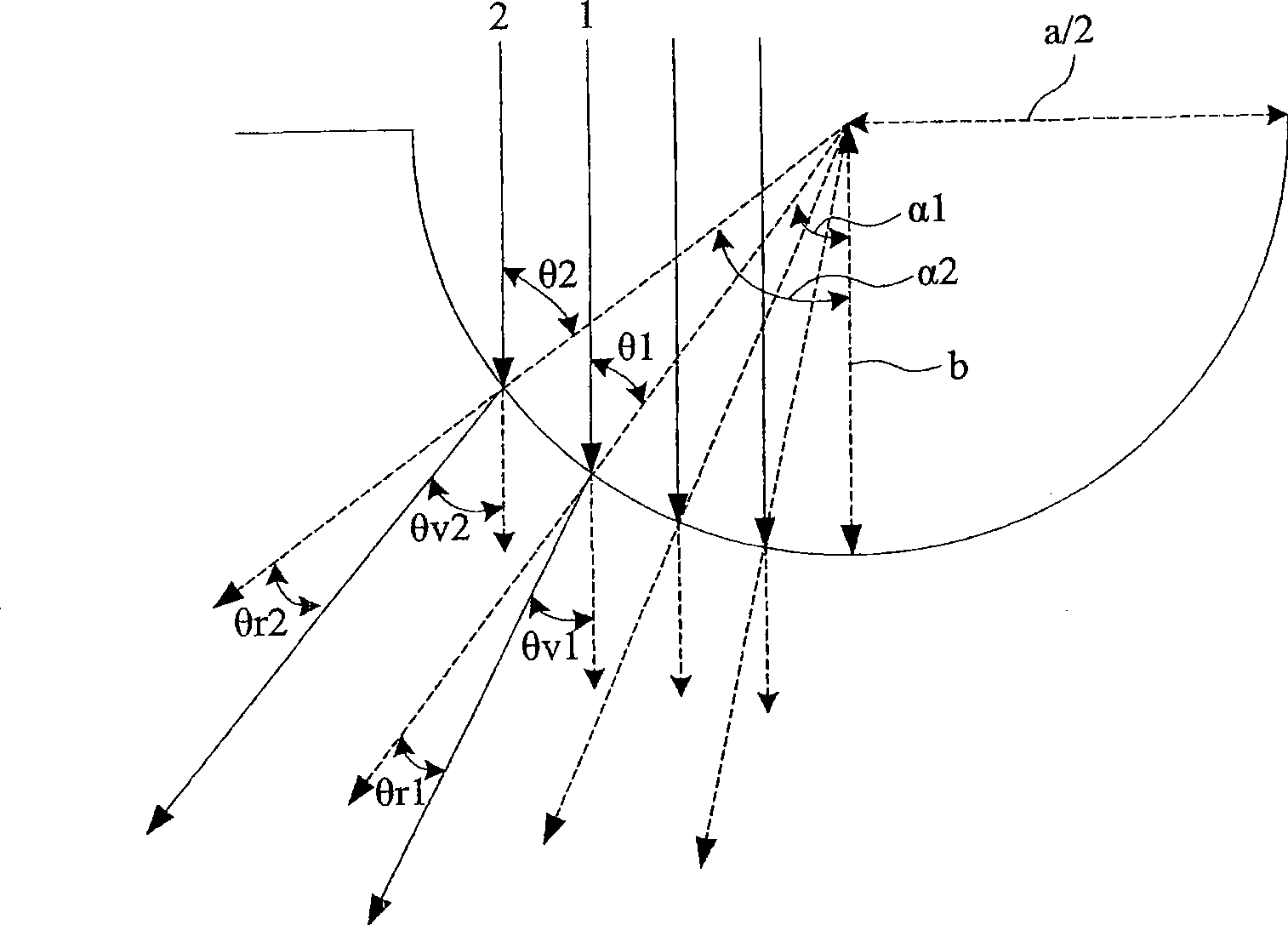
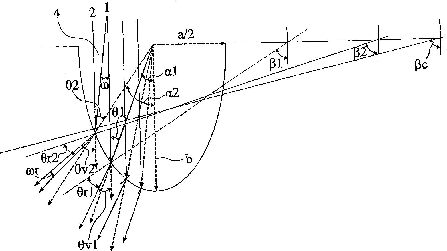
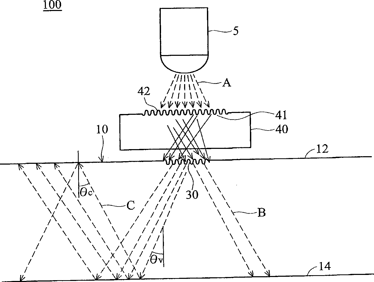
[0042] The composite light-guiding film module of the present invention mainly arranges a refraction member above a light-guiding film. After the light passes through the refracting member, a larger incident angle is generated, so that the light enters the light-guiding film and then passes through the light-guiding film. The total reflection is done in the diaphragm, and the larger the incident angle of the light will increase the amount of light transmitted by the total reflection of the light in the light guide diaphragm, reducing the loss of light due to penetration and scattering. The following is the relevant analysis.

[0043] figure 1 , 2 is a schematic diagram of light passing through a micro-concave lens structure.

[0044] figure 1 For the case of light passing through a hemispherical dimple lens.

[0045] 1, 2: Beam

[0046] a / 2: dimple lens aperture

[0047] b: Micro-concave lens depth

[0048] n1: air refractive index

[0049] n2: Refractive index of micro...


PUM


Abstract

A composite light guide film module comprises a light guide film, a light diffusing structure and an optical refracting element, wherein the light diffusing structure arranged on the surface of the light guide film comprises a plurality of micro-concave lenses which are arranged into one-dimensional and two-dimensional arrays along a first direction and a second direction, curvatures of both the lens faces of the micro-concave lenses and the joints among the micro-concave lenses are not zero, and the optical refracting element comprises at least one optical refracting structure. After optical fraction, light from one light source passes through the light diffusing structure to enter the light guide film, and then is totally reflected inside the light guide film for transmission.

Description

technical field [0001] The present invention relates to a composite light-guiding film module, in particular to a composite light-guiding film module that combines multiple optical components so that light can be directly introduced into the interior of the film from the surface of the light-guiding film, and the light can be transmitted along the interior . Background technique [0002] Generally, small and medium-sized backlights, including mobile phones, PDAs, digital cameras, etc., mainly use side-light light-guiding backlight modules. Because small sizes pursue lightness, thinness, shortness, and even flexibility, thinning is a trend in product design. Backlights The source group is also constantly reducing its thickness. Ultra-thin light guide film is the main focus of technological development in various countries. There are many low-efficiency or ineffective light guide film products on the market, which only provide light diffusion, reflection or partial light coupl...

Claims


Application Information

Patent Timeline
Patent Type & Authority Applications(China)
IPC IPC(8): G02F1/13357G02B6/00G02B5/00B32B7/02
Inventor 赵志强萧柏龄曾宇璨赖美君
Owner IND TECH RES INST
Why Eureka
Try Eureka