Continuous sheet processing apparatus

a technology of continuous sheets and processing equipment, which is applied in the direction of web handling, transportation and packaging, pile separation, etc., can solve the problems of difficult to throw in the roll body, and the drawn-out portion of the continuous sheet cannot be held in some cases, so as to prevent the lifting up of the roll body and facilitate the effect of throwing in

Inactive Publication Date: 2009-04-02
SEIKO INSTR INC
View PDF6 Cites 4 Cited by
  • Summary
  • Abstract
  • Description
  • Claims
  • Application Information

AI Technical Summary

Benefits of technology

[0009]The present invention has been made in view of the above-mentioned conventional problems, and an object of the present invention is to provide a continuous sheet processing apparatus in which the lifting-up of the roll body can be prevented, the roll body can be easily thrown-in, the defects are less liable to be caused, and the drawing-out angle of the continuous sheet can be reliably made acute.

Problems solved by technology

Thus, there is a problem in that the roll body is difficult to throw-in because the guide portion presents as an obstruct in opening the door portion for throwing-in the roll body.
However, the following problem is expected: the link mechanism provided to the door portion is positioned while allowing to be touched by a user at the time of replacing the roll body, thereby involving defects (deformation and the like) of the link mechanism caused by the user.
When the defects occur in the link mechanism, the guide portion is not turned, so the drawn-out portion of the continuous sheet cannot be held in some cases.

Method used


Image

  • Continuous sheet processing apparatus
  • Continuous sheet processing apparatus
  • Continuous sheet processing apparatus

Examples


Embodiment Construction

[0045]Hereinafter, with reference to the drawings, an embodiment of the continuous sheet processing apparatus according to the present invention is described.

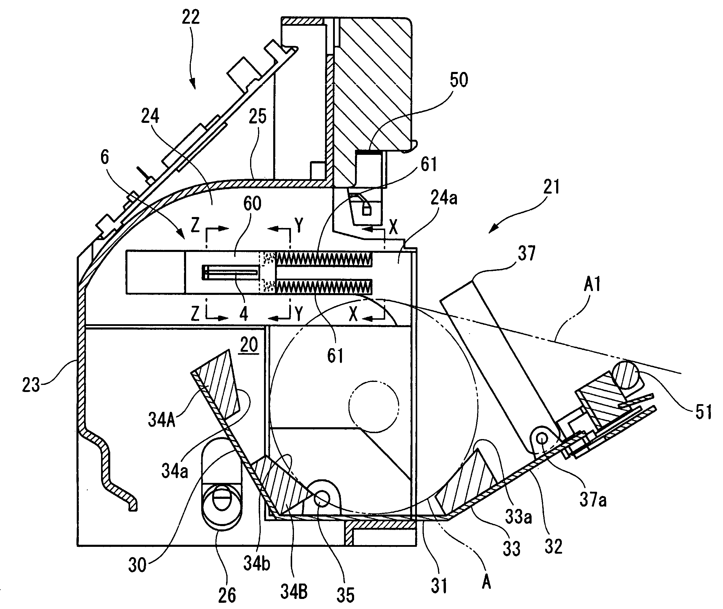
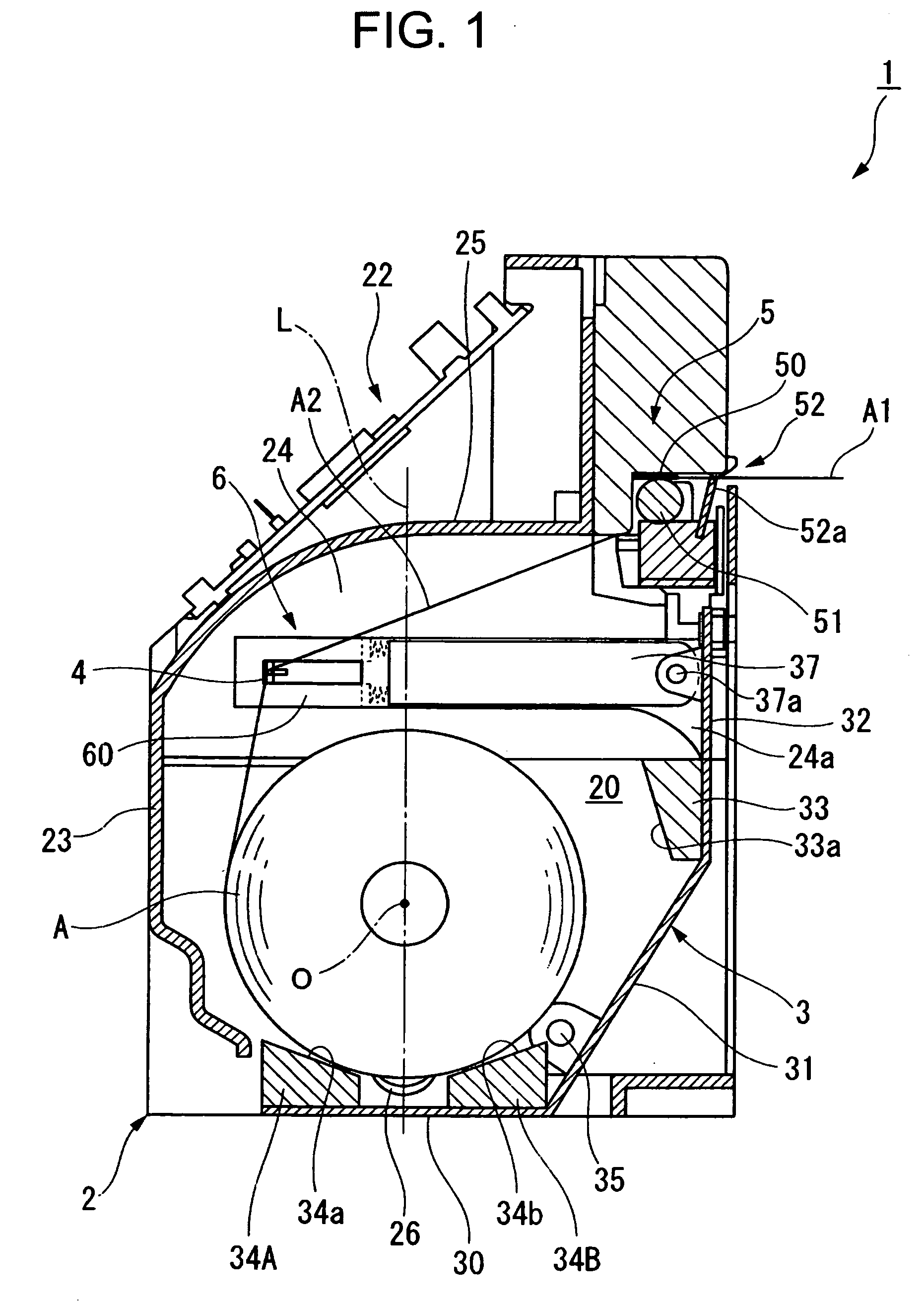
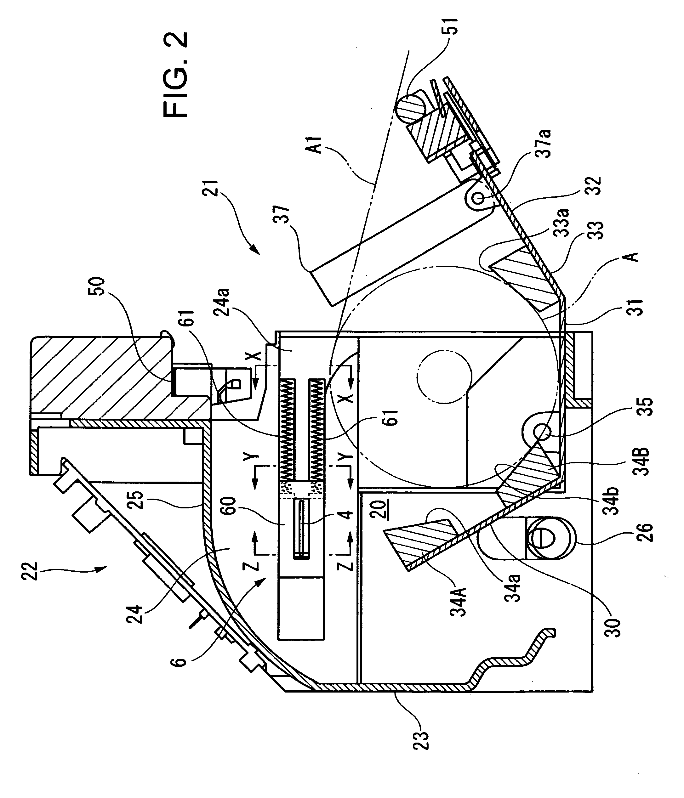
[0046]FIG. 1 is a sectional view of a continuous sheet processing apparatus 1 in the state where a door portion 3 described later is closed, and FIG. 2 is a sectional view of the continuous sheet processing apparatus 1 in the state where the door portion 3 described later is opened. Note that, in the embodiment of the present invention, it is assumed that the left side of FIGS. 1 and 2 is rear (corresponding to one side of the present invention), the right side of FIGS. 1 and 2 is front (corresponding to the other side of the present invention), and the longitudinal direction of FIGS. 1 and 2 is the vertical direction. Further, a chain line L extending in the vertical direction illustrated in FIG. 1 is a virtual line illustrating a center reference line orthogonal to a center axis line O of a roll body A described later. The ce...


PUM

PropertyMeasurementUnit
pressureaaaaaaaaaa
depthaaaaaaaaaa
angleaaaaaaaaaa

Abstract

In order to prevent lifting-up of a roll body, facilitate throwing-in of the roll body, make defects less liable to occur, and reliably make a drawing-out angle of a continuous sheet acute, a continuous sheet processing apparatus 1 comprises a main body portion 2 having a roll body accommodating chamber 20 and a roll body inlet 21; a door portion 3 for opening and closing the roll body inlet 21; a guide portion 4 disposed on one side with respect to a center reference line L orthogonal to a center axis line O of the roll body A accommodated in the roll body accommodating chamber 20, for holding from another side a drawn-out portion A2 of a continuous sheet A1 drawn out of a portion on the one side with respect to the center reference line L; and a processing portion 5 disposed on the another side with respect to the center reference line L, for processing the continuous sheet A1, a guide portion moving means 6 is provided for moving the guide portion 4 between a first position at which the guide portion 4 holds the drawn-out portion A2 from the other side and a second position at which the guide portion 4 is led out of a space between the drawn-out portion A2 and the roll body A; and the guide portion 4 and the guide portion moving means 6 are arranged in the roll body accommodating chamber20.

Description

BACKGROUND OF THE INVENTION[0001]1. Field of the Invention[0002]The present invention relates to a continuous sheet processing apparatus in which printing, thermal activation, and the like are performed on a continuous sheet.[0003]2. Description of the Related Art[0004]Conventionally, a continuous sheet processing apparatus is well-known in which a continuous sheet is sequentially sent forth from a roll body, the sent-forth continuous sheet is subject to printing, thermal activation, and the like, and a processed portion is cut to provide single-cut sheets.[0005]Examples of the continuous sheet processing apparatus include, as disclosed in Patent Document JP 2004-306561 A, one of a so-called throw-in type which merely accommodates a roll body without supporting a core of the roll body. The continuous sheet processing apparatus includes a roll body accommodating chamber in a main body portion thereof, and a roll body inlet formed in the front surface of the main body portion. Further...

Claims


Application Information

Patent Timeline
Patent Type & Authority Applications(United States)
IPC IPC(8): B65H9/00
CPCB41J15/04B41J15/042B65H2801/12B65H2402/31B65H2402/542B65H2301/41386B65H2402/54B65H23/032
Inventor YOKOYAMA, YASUMI
Owner SEIKO INSTR INC
Why Eureka
Try Eureka