
Method of manufacturing cmc articles having small complex features

a technology of ceramic matrix and composite gas turbine engine, which is applied in the direction of machines/engines, sustainable transportation, mechanical equipment, etc., can solve the problems of less directional inserts made from discontinuously reinforced composites, while having properties, and cured cmc lay-ups, so as to reduce the complexity of lay-ups, and reduce the cost of manufacturing

Inactive Publication Date: 2009-07-02
GENERAL ELECTRIC CO
View PDF17 Cites 42 Cited by
  • Summary
  • Abstract
  • Description
  • Claims
  • Application Information

AI Technical Summary

Benefits of technology

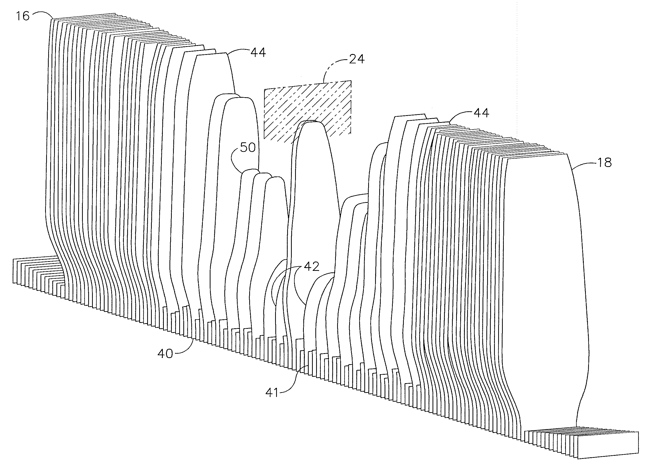
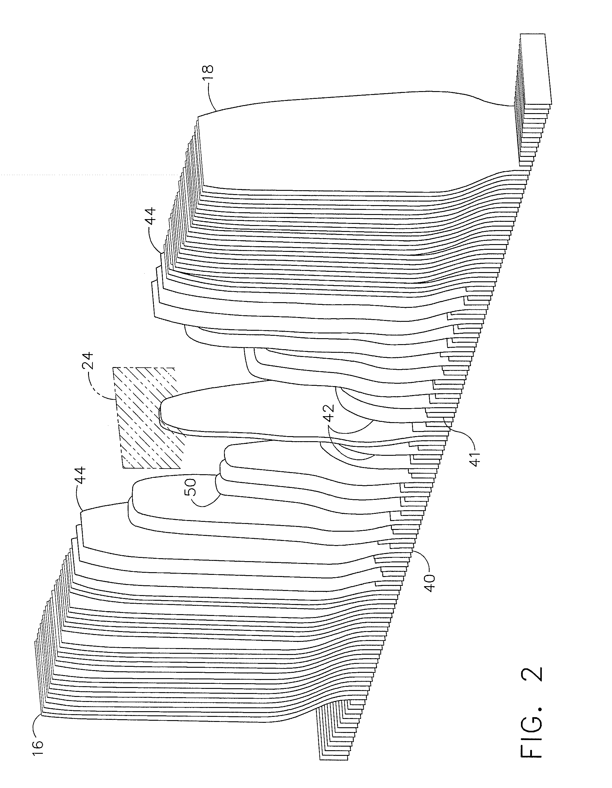
[0016]An advantage of the present invention is that a plurality of small, cut fabric plies can be replaced by a single discontinuously reinforced composite insert. The discontinuously reinforced composite insert can be provided as a material having substantially isotropic properties.
[0017]Another advantage of the present invention is that manufacture of an aircraft engine component can be simplified by elimination of a complex, time consuming lay-up scheme, while providing a component satisfying stress analysis requirements.
[0018]Another advantage of the present invention is that the methods result in an increase in the production rate while providing fewer components with defects.
[0019]Yet another advantage of the present invention is that the use of discontinuously reinforced composite inserts will allow for the inclusion of fine features, such as thin sections and small radii, to enable functionality and performance at higher operating temperatures.

Problems solved by technology

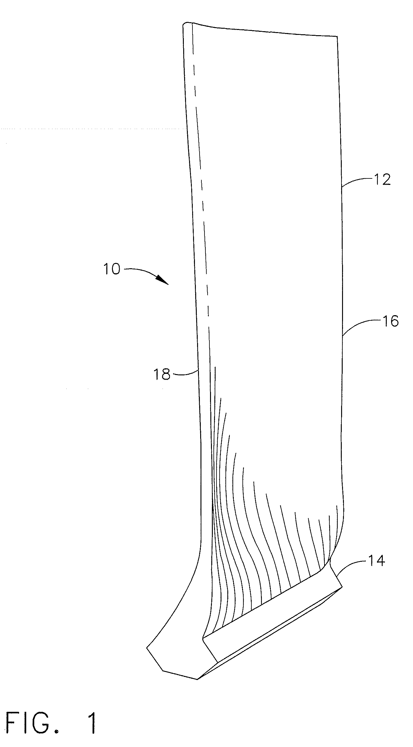
However, in areas where complex features are present, discontinuously reinforced composite inserts are incorporated into the component, so that the turbine component is a combination of prepreg layers and discontinuously reinforced composite inserts.
Since discontinuously reinforced composite inserts do not have the directional strength of laid up plies, modeling is required to properly ascertain regions in which the inserts can replace plies without adversely affecting the component.
Inserts made from discontinuously reinforced composite, while having properties that are not quite isotropic, nevertheless are less directional than a cured CMC lay-up.

Method used


Image

  • Method of manufacturing cmc articles having small complex features
  • Method of manufacturing cmc articles having small complex features
  • Method of manufacturing cmc articles having small complex features

Examples


example 1

[0040]A slurry was prepared by utilization of SiC / SiC unidirectional prepreg tape, the tape being a coated silicon carbide tow in a silicon carbide matrix. The fibers comprising the tow typically are coated with a debond coating such as boron nitride. The backing was removed from the prepreg by exposing the fabric to liquid nitrogen. The fabric was then cut into pieces having a size of about ¼ square in. and smaller. A proprietary solution of Cotronics Resbond 931, a high temperature ceramic graphite adhesive resin available from Cotronics Corp. of Brooklyn N.Y. and acetone was prepared by mixing with an equal weight of acetone. The chopped prepreg, about 3 g, was added to the solution in a weight ratio of about 3:1 prepreg:solution to form a mixture. The mixture was blended by a suitable means to achieve a uniform consistency. This can be achieved by shaking, stirring, ball milling or other mixing techniques. The viscosity of the mixture can be adjusted as required consistent with ...


PUM

PropertyMeasurementUnit
diametersaaaaaaaaaa
diametersaaaaaaaaaa
thicknessaaaaaaaaaa

Abstract

A method for forming a ceramic matrix composite (CMC) component for gas turbine engines. The method contemplates replacing a plurality of plies with insert material. The insert material can be partially cured or pre-cured and applied in place of a plurality of small plies or it may be inserted into cavities of a component in the form of a paste or a ply. The insert material is isotropic, being formed of a combination of matrix material and chopped fibers, tow, cut plies or combinations thereof. The use of the insert material allows for features such as thin edges with thicknesses of less than about 0.030 inches and small radii such as found in corners. The CMC components of the present invention replace small ply inserts cut to size to fit into areas of contour change or thickness change, and replace the small ply inserts with a fabricated single piece discontinuously reinforced composite insert, resulting in fewer defects, such as wrinkles, and better dimensional control.

Description

CROSS REFERENCE TO RELATED APPLICATIONS[0001]This application is related to co-pending application identified as Attorney Docket No. 162832 (07783-0272) and entitled CMC ARTICLES HAVING SMALL COMPLEX FEATURES, assigned to the assignee of the present invention and filed on even date with the present inventionFIELD OF THE INVENTION[0002]The present invention relates generally to a method of manufacturing ceramic matrix turbine engine components, and more particularly, to a method of manufacturing a ceramic matrix composite gas turbine engine component having small complex features.BACKGROUND OF THE INVENTION[0003]In order to increase the efficiency and the performance of gas turbine engines so as to provide increased thrust-to-weight ratios, lower emissions and improved specific fuel consumption, engine turbines are tasked to operate at higher temperatures. The higher temperatures reach and surpass the limits of the material comprising the components in the hot section of the engine. ...

Claims


Application Information

Patent Timeline
Patent Type & Authority Applications(United States)
IPC IPC(8): C03B29/00
CPCF01D5/147F05C2203/0839Y02T50/67Y02T50/672F05D2300/614F05D2300/2283F05D2300/2261F05D2300/44F05D2300/603F05D2300/21Y02T50/60
Inventor STEIBEL, JAMES DALECARPER, DOUGLAS MELTONSUBRAMANIAN, SURESHWHITEKER, STEPHEN MARK
Owner GENERAL ELECTRIC CO
Learn More