
Transmission mechanism for stamping die

A technology of transmission mechanism and stamping die, which is applied in the field of stamping die accessories, can solve the problems of scratches on the cover, lower yield rate, inability to maximize the contact surface between the car cover and the belt, etc., and achieve the effect of stable transmission

Active Publication Date: 2014-09-03
ANHUI JIANGHUAI AUTOMOBILE GRP CORP LTD
View PDF12 Cites 1 Cited by
  • Summary
  • Abstract
  • Description
  • Claims
  • Application Information

AI Technical Summary

Problems solved by technology

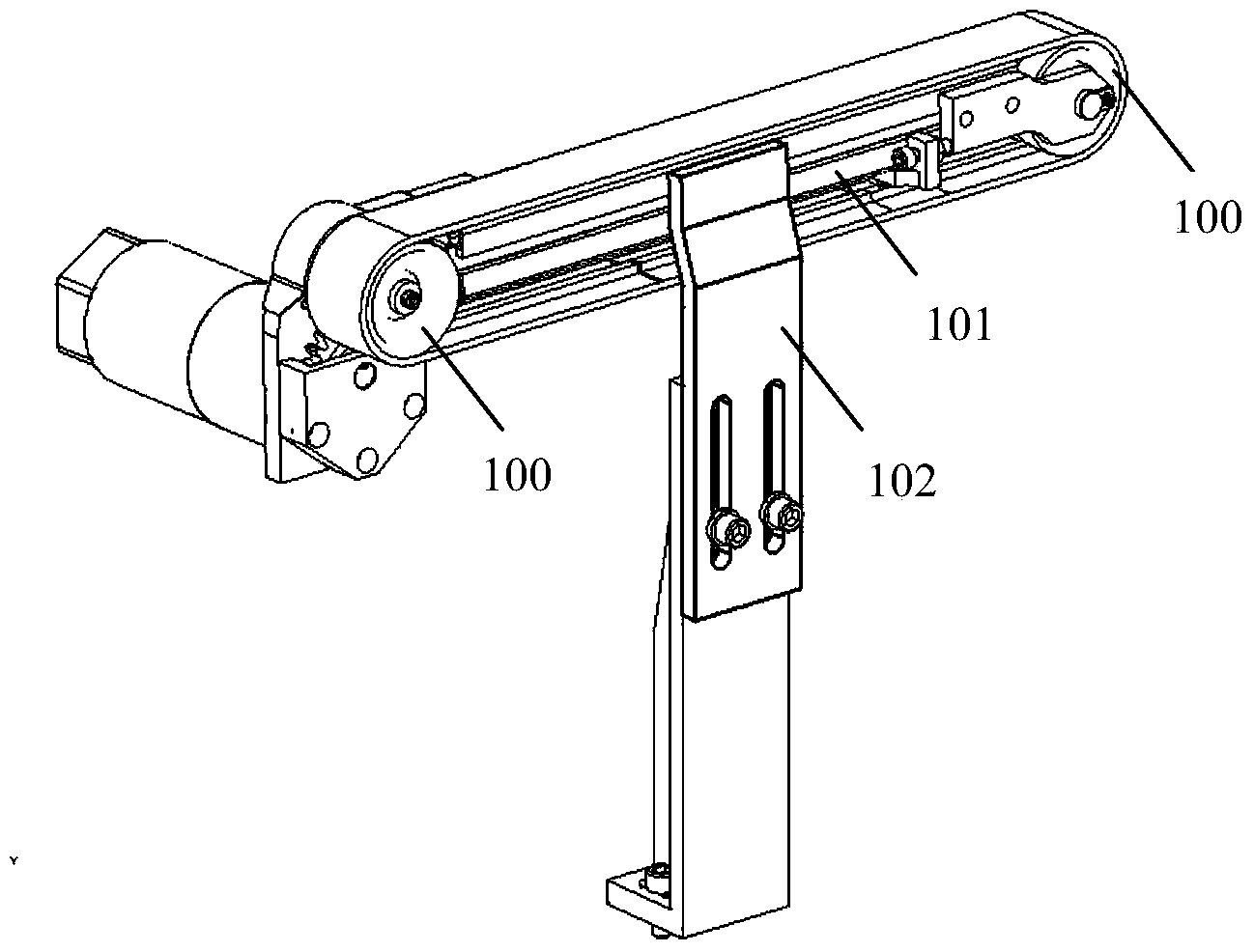
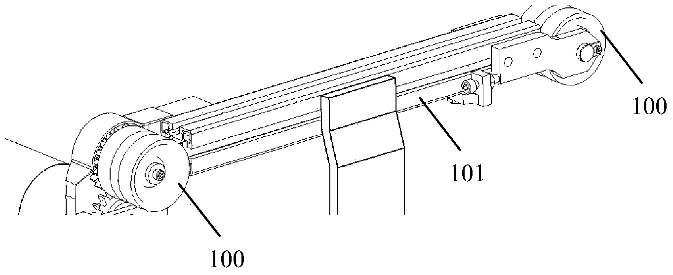
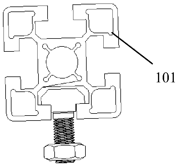
This structure makes it impossible to adjust between the pulley 100 and the profile 101 and between the profile 101 and the connecting plate 102, so that the transmission mechanism cannot maximize the contact surface between the automobile cover and the belt, especially for the cover with large undulations , the belt in the existing transmission mechanism cannot fit the cover as much as possible. Therefore, the situation that the belt cannot drive the cover will occur during the transmission process, and the rigid parts on the transmission mechanism are easy to cause scratches on the cover, affecting The surface quality of the covering parts reduces the yield rate

Method used


Image

  • Transmission mechanism for stamping die
  • Transmission mechanism for stamping die
  • Transmission mechanism for stamping die

Examples


Embodiment Construction

[0034] Below in conjunction with accompanying drawing and specific embodiment the present invention is described in further detail:

[0035] Such as Figure 4 As shown, a transmission mechanism for stamping dies, which is mainly used in stamping dies for automobile stamping parts, including driving wheel 1, driven wheel 2, belt 3, motor 4, round shaft 5, open clamp 6, connecting plate 7.

[0036] Belt 3 Tensioned belt 3 on driving pulley 1 and driven pulley 2.

[0037] The circular shaft 5 is arranged between the driving wheel 1 and the driven wheel 2, and its axis is parallel to the working surface of the belt 3.

[0038] Four open clamps 6 are clamped on the round shaft 5 , two of which are respectively arranged at both ends of the round shaft 5 , and a motor 4 is mounted on the open clamp 6 close to the driving wheel 1 .

[0039] The non-open ends of two opening clamps 6 on the circular shaft 5 middle part are installed on this connecting plate 7 in a vertically adjustab...


PUM


Abstract

The invention discloses a transmission mechanism for a stamping die. The transmission mechanism comprises a driving wheel, a driven wheel, a belt arranged on the driving wheel and the driven wheel in a tensioning mode, a circular shaft arranged between the driving wheel and the driven wheel, a plurality of opened clamps which are arranged on the circular shaft in a clamping mode, and a joining plate, wherein the axis of the circular shaft is parallel to the working face of the belt, and the non-opened end of at least one opened clamp is adjustably installed on the joining plate relative to the perpendicular direction of the joining plate. According to the transmission mechanism for the stamping die, the circular shaft in the transmission mechanism can rotate in the opened clamps so that normal adjustment of the circular shaft and the upper potion of the joining plate can be achieved, the opened clamps and the joining plate can be adjusted in the perpendicular direction so that the working face on the belt can be adjusted according to the molded surface of a covering part of an automobile, contact maximum of the covering part of the automobile and the conveying belt is achieved, and fast and stable conveying is ensured under the premise that the covering part is not damaged.

Description

technical field [0001] The invention belongs to stamping die accessories, in particular to a transmission mechanism for stamping dies. Background technique [0002] In order to meet the needs of strength, function, shape and other aspects, automobile panels are often very complex in shape. In order to ensure the surface quality of complex-shaped covers, extreme care must be taken during the transfer process, and the convenience of cover transfers will directly affect the efficiency of stamping production. Therefore, how to make the transmission mechanism to complete the fast, stable and non-damaging transmission of the cover has become a key link in the stamping production process. [0003] Such as Figure 1 to Figure 3 As shown, the two pulleys 100 of the existing transmission mechanism are connected through profiles 101 . The profile of profile 101 is as image 3 shown. The profile 101 is welded to the connecting plate 102 . This structure makes it impossible to adjus...

Claims


Application Information

Patent Timeline
IPC IPC(8): B21D43/12
Inventor 何鹏申刘春雨阮林凡郑薇赵鸿鹄赖荣胜王海玲
Owner ANHUI JIANGHUAI AUTOMOBILE GRP CORP LTD
Learn More