

Twin-needle machine binding off mechanism
A double-needle car and one-pair technology, which is applied to sewing machine components, sewing machine control devices, textiles and papermaking, etc., can solve the problems of difficult adjustment of the mechanism and unstable transmission of the overlay system, so as to improve production efficiency, improve structure, The effect of smooth transmission
- Summary
- Abstract
- Description
- Claims
- Application Information
AI Technical Summary
Problems solved by technology
Method used
Image

Examples
Embodiment Construction
[0012] The preferred embodiments of the present invention will be described in detail below in conjunction with the accompanying drawings, so that the advantages and features of the present invention can be more easily understood by those skilled in the art, so as to define the protection scope of the present invention more clearly.
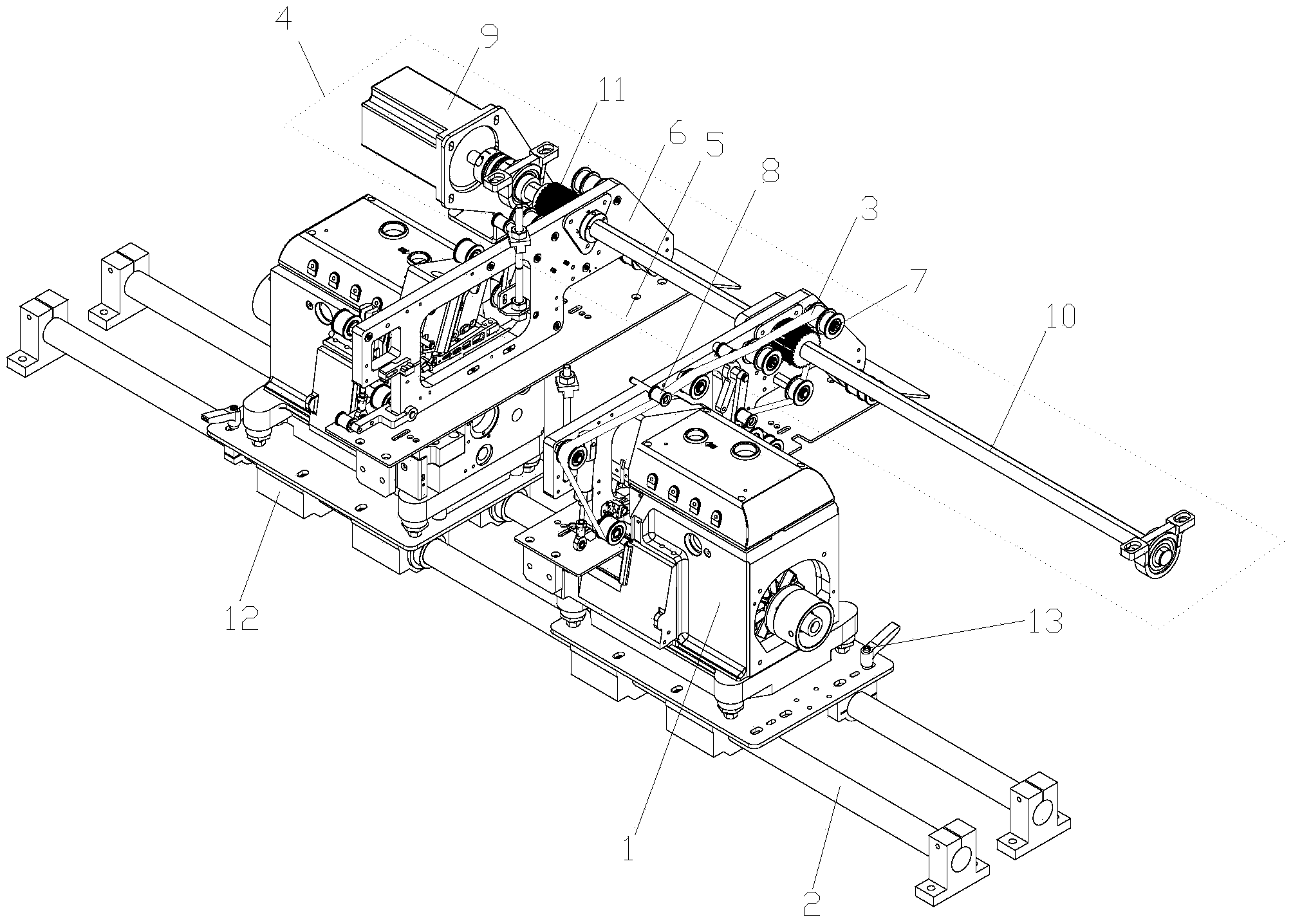
[0013] Please refer to the attached figure 1 , the embodiment of the present invention includes:
[0014] A double-needle car edge overlay mechanism includes a pair of double-needle cars 1 facing opposite each other, a sliding track 2, a carrier, a belt 3 and a synchronous transmission assembly 4 fixed on the carrier. A pair of double-needle machines 1 are all set on the sliding track 2 to carry out double-sided overlaying of the cloth passing between the two, and each double-needle machine 1 can relatively slide on the sliding track 2 . The head of the double-needle car 1 is fixed with a carrier, because the carrier is used to assist the croche...
PUM
 Abstract
Description
Claims
Application Information