Control system of automatic revolving door

An automatic rotation and door control technology, applied in door/window accessories, power control mechanisms, buildings, etc., can solve the problems of inability to control the output torque of the motor, limited selectivity of the revolving door motor, and complex control system, and achieve easy Installation and debugging, low noise, high transmission efficiency

Inactive Publication Date: 2017-01-25
唐晓辉
View PDF5 Cites 7 Cited by
  • Summary
  • Abstract
  • Description
  • Claims
  • Application Information

AI Technical Summary

Problems solved by technology

There are the following deficiencies in technology: 1. AC asynchronous motors generally adopt frequency conversion control, which has poor low-speed performance and low power factor, which is not conducive to energy saving and consumption reduction
2. The AC asynchronous motor control system adopts the inverter + PLC structure, the control system is complicated, the cost is high, and because the motor drive and the door control are separated, the output torque of the motor cannot be controlled.

Method used


Image

  • Control system of automatic revolving door
  • Control system of automatic revolving door

Examples


Example Embodiment

[0021] Example one:

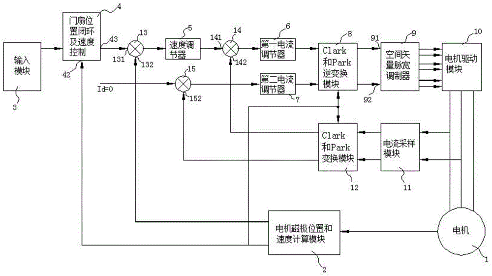
[0022] An automatic revolving door control system, its structure block diagram is as follows figure 1 As shown, the control system of the present invention provides a rotation speed value through the input module 3. The motor magnetic pole position and speed calculation module 2 respectively provide position feedback signals to the door leaf position closed loop and the feedback terminal 42 of the speed control 4, and provide speed feedback signals to the first The feedback terminal 132 of the node 13 and the sampling signal value of the current sampling module 11 are transformed by the Park and Clark transformation module 12 to the feedback terminals 152 and 142 of the third node 15 and the second node 14. Door leaf position closed loop and speed control 4 According to the input status of the input module 3, the speed setting value is output to the output terminal 43. The difference between the speed setting value and the feedback value is sent to the speed ...

Example Embodiment

[0028] Embodiment two:

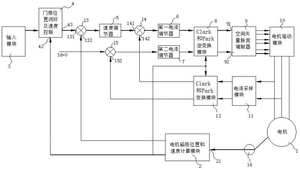
[0029] An automatic revolving door control system, its structure block diagram is as follows figure 2 As shown, the difference from the first embodiment is that the output end of the motor 1 of the control system of the present invention includes a magnetic induction encoder 16 mounted on the motor 1, and the output end of the magnetic induction encoder 16 is concentric with the rotor of the motor 1. The output terminal of the magnetic induction encoder 16 is connected to the input terminal 21 of the motor magnetic pole position and speed calculation module 2, and the induction magnet connected to the magnetic induction encoder 16 is installed on the shaft of the motor 1, and the rotation of the rotor of the motor 1 induces The magnetic steel rotates at the same center as the rotor of the motor 1 with respect to the magnetic induction encoder 16, wherein the magnetic induction encoder 16 measures the operating state of the motor 1 through the induction m...


PUM


Abstract

The invention discloses a control system of automatic revolving door. The control system, which adopts a closed-loop control structure formed by location, speed and current, comprises an input module, a closed loop and speed controller of door leaf, a speed governor, a first current regulator, a second current regulator, a reverse transformation module, a space vector pulse width modulator, a motor driven module, a current sampling module, a signal conversion module, a motor, and a module for calculation of pole location and speed of the motor; the control flow is: first, a setting signal is provided to the closed-loop control formed by location, speed, and current; second, the output signal of the closed-loop control goes through the space vector pulse width modulator and reverse transformation module and forms the three-phase AC signal of the drive motor; finally, terminal voltage and phase current of the motor are acquired by the sampling module and processed by the signal conversion module to be the feedback signal of the closed-loop control structure. The control system of automatic revolving door is energy saving and environmental friendly, low in noise, reliable in operation, easy to install and debug, and has the anti-clip function.

Description

technical field [0001] The invention relates to the field of automatic door technical equipment, in particular to an automatic revolving door control system. Background technique [0002] With the development of social economy, the advancement of science and technology and the gradual improvement of people's living standards, automatic revolving doors are increasingly used in enterprises and public places. With the expansion of the application field of revolving doors, the market demand for automatic revolving doors has increased, resulting in new requirements for the controllability and safety of the revolving door control system. In response to the call of the national scientific outlook on development, energy conservation and environmental protection have also become a top priority. [0003] Most of the revolving door control systems on the market use AC asynchronous motor control systems. There are the following deficiencies in technology: 1. AC asynchronous motors gen...

Claims


Application Information

Patent Timeline
IPC IPC(8): E05F15/70E05F15/40E05F15/608
Inventor 唐晓辉
Owner 唐晓辉
Why Eureka
Try Eureka