
A metal pipe cutting device

A cutting device, metal pipe technology, applied in the direction of pipe shearing device, shearing device, metal processing equipment, etc., can solve the problem of uneven incision and so on

Active Publication Date: 2016-09-21
DONGQING TECH
View PDF5 Cites 0 Cited by
  • Summary
  • Abstract
  • Description
  • Claims
  • Application Information

AI Technical Summary

Problems solved by technology

[0002] At present, in general pipe processing, in order to meet the needs of pipe fitting design, in addition to repairing the weld part of the pipe fitting, it also includes a cutting step according to the length of the pipe fitting design. This step can be combined with the welding seam part The repair is carried out continuously. When actually cutting the metal pipe, the method usually used is to pull out the metal pipe to be cut section by section, and the cutting knife is fixed and falls in the interval time. Since the cutting knife is not synchronized, it is easy to cause the incision to be uneven. not smooth

Method used


Image

  • A metal pipe cutting device

Examples


Embodiment Construction

[0012] Embodiments of the present invention are described in detail below, examples of which are shown in the drawings, wherein the same or similar reference numerals designate the same or similar elements or elements having the same or similar functions throughout. The embodiments described below by referring to the figures are exemplary only for explaining the present invention and should not be construed as limiting the present invention.

[0013] In the description of the present invention, unless otherwise specified and limited, it should be noted that the terms "installation", "connection" and "connection" should be understood in a broad sense, for example, it can be mechanical connection or electrical connection, or two The internal communication of a component can be directly connected or indirectly connected through an intermediary. Those of ordinary skill in the art can understand the specific meanings of the above terms according to specific situations.

[0014] Re...


PUM


Abstract

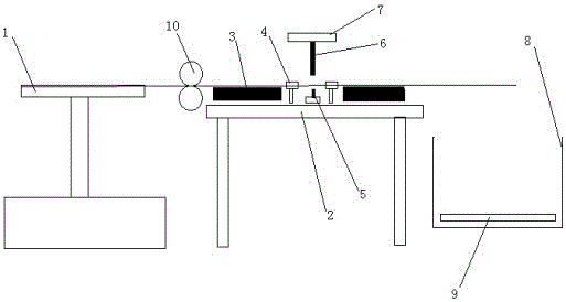
A metal pipe cutting device, including a machine base, the active discharge tray of the cutting device is set on the side of the machine base, two transmission rollers are arranged between the active discharge tray and the machine base to assist in discharging materials, and the upper surface of the machine base is set There are two transmission tracks, the transmission track, the transmission roller and the active discharge tray are driven by the same motor, and the motor uses gear transmission to transmit power. There are two pneumatic clamps between the two transmission tracks, and the two pneumatic clamps are controlled by Driven by the same cylinder, the pipe to be cut moves forward under the action of the two transmission rails and passes through the two pneumatic clamps. The mouth of the pipe clamped by the two pneumatic clamps is on the same level as the two transmission rails. The transmission track is set on the machine base, and the pneumatic clamp is set between the transmission tracks. Since the cylinder is used to provide power, it will not cause damage to the metal pipe, because the transmission of the metal pipe has been stopped. At this time, the metal pipe is still relative to the cutter. The incision is very smooth.

Description

technical field [0001] The invention relates to the field of metal cutting, in particular to a metal pipe cutting device. Background technique [0002] At present, in general pipe processing, in order to meet the needs of pipe fitting design, in addition to repairing the weld part of the pipe fitting, it also includes a cutting step according to the length of the pipe fitting design. This step can be combined with the welding seam part The repair is carried out continuously. When actually cutting the metal pipe, the method usually used is to pull out the metal pipe to be cut section by section, and the cutting knife is fixed and falls in the interval time. Since the cutting knife is not synchronized, it is easy to cause the incision to be uneven. Not smooth. Contents of the invention [0003] The present invention aims to provide a metal pipe cutting device. [0004] In order to achieve the above-mentioned technical purpose, the present invention adopts the following tec...

Claims


Application Information

Patent Timeline
Patent Type & Authority Patents(China)
IPC IPC(8): B23D21/00
Inventor 赵烨
Owner DONGQING TECH
Learn More