Installation structure for automobile radiator

An automobile radiator and installation structure technology, which is applied in the direction of the combination of power unit cooling, power unit, vehicle components, etc., can solve problems such as difficult installation, weak anti-torsion strength, and blind spots in installation

Inactive Publication Date: 2014-09-03
CHONGQING CHANGAN AUTOMOBILE CO LTD
View PDF9 Cites 4 Cited by
  • Summary
  • Abstract
  • Description
  • Claims
  • Application Information

AI Technical Summary

Problems solved by technology

The main defects of this car radiator mounting structure are: in the assembly process, the lower mounting plate 4 and the radiator 3 need to be assembled into a whole, and then lifted from the bottom to the top, and the two ends of the lower mounting plate 4 Connect with the lower ends of the left bracket 5 and the right bracket 2, and then connect the top surface of ...

Method used


Image

  • Installation structure for automobile radiator
  • Installation structure for automobile radiator
  • Installation structure for automobile radiator

Examples


Embodiment Construction

[0023] The present invention will be described in further detail below in conjunction with accompanying drawing and specific embodiment;

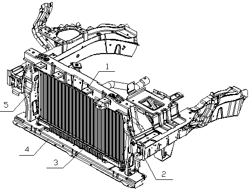
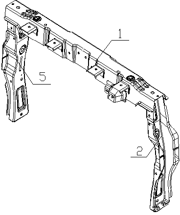
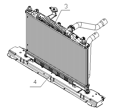
[0024] see Figure 4 , the automobile radiator mounting structure of the present invention comprises an upper mounting plate 1, a lower mounting plate 4, a left bracket 5 and a right bracket 2, and the upper and lower ends of the left bracket 5 and the right bracket 2 are respectively connected to the upper mounting plate The left and right ends of the plate 1 and the lower mounting plate 4 are connected, the middle and lower parts are connected with the left and right engine compartment side beams, the bottom surface of the radiator 3 is assembled on the lower mounting plate 4, and the top surface is connected with the upper mounting plate 1. From Figure 4 It can be seen that the present invention also includes the left front cover plate 11 of the engine compartment side beam and the right front cover plate 9 of the engine compartment si...


PUM


Abstract

The invention discloses an installation structure for an automobile radiator. The installation structure comprises an upper installation plate (1), a lower installation plate (4), a left bracket (5) and a right bracket (2). The upper end and the lower end of the left bracket (5) and the upper end and the lower end of the right bracket (2) are connected with the left end and the right end of the upper installation plate (1) and the left end and the right end of the lower installation plate (4) respectively. The lower middle portion of the left bracket (5) and the lower middle portion of the right bracket (2) are connected with a left engine compartment boundary beam and a right engine compartment boundary beam. The bottom face of the radiator (3) is assembled on the lower installation plate (4), and the top face of the radiator (3) is connected with the upper installation plate (1). The installation structure is characterized by further comprising an engine compartment boundary beam left front sealing plate (11) and an engine compartment boundary beam right front sealing plate (9), and the lower middle portion of the left bracket (5) and the lower middle portion of the right bracket (2) are connected with the left engine compartment boundary beam and the right engine compartment boundary beam respectively through the engine compartment boundary beam left front sealing plate (11) and the engine compartment boundary beam right front sealing plate (9). According to the installation structure for the automobile radiator, the radiator can be placed and assembled from top to bottom, installation is easier, and no dead zones exist.

Description

technical field [0001] The invention relates to an automobile body structure, in particular to an automobile radiator installation structure. Background technique [0002] Existing car radiator installation structure, see figure 1 , usually including an upper mounting plate 1, a lower mounting plate 4, a left bracket 5 and a right bracket 2; The left and right ends are connected, the middle and lower parts are connected with the side beam of the engine compartment, the bottom surface of the radiator 3 is assembled on the lower mounting plate 4, and the top surface is connected with the upper mounting plate 1. In this car radiator installation structure, since the middle and lower parts of the left bracket 5 and the right bracket 2 are directly connected to the side beam of the engine compartment, it is necessary to install the radiator 3 in the following order: the first step, see figure 2 , weld the upper ends of the left bracket 5 and the right bracket 2 to the left and...

Claims


Application Information

Patent Timeline
IPC IPC(8): B60K11/04
Inventor 朱家修孙晖常满红赵明张景伟
Owner CHONGQING CHANGAN AUTOMOBILE CO LTD
Why Eureka
Try Eureka