

Tube packing machine
A packaging machine and pipe technology, applied in the field of packaging equipment, can solve the problems of low work efficiency of manual bagging, and achieve the effects of avoiding scratches on pipes, easy implementation, and small space occupation
- Summary
- Abstract
- Description
- Claims
- Application Information
AI Technical Summary
Problems solved by technology
Method used
Image

Examples
Embodiment 1
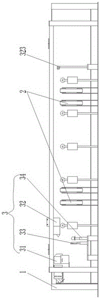
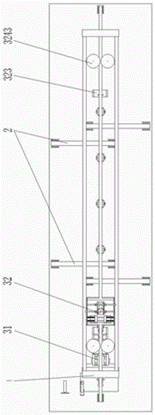
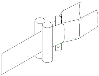
[0036] Embodiment one: see Figure 1~Figure 13, as can be seen from the figure, the pipe packing machine includes a frame 1, a feeding mechanism 2 and a packaging device 3; 4. A bagging device 32 clamped and placed on the pipe 5, and a set of bag cutting mechanism 33 for cutting the packaging bag 4 wrapped on the pipe 5; The bag mechanism 33 can be arranged between the bag opening mechanism 31 and the material delivery mechanism 2; Between the bag-cutting mechanism 33 and the feeding mechanism 2; wherein, the anti-scratch mechanism 34 mainly consists of the ball-holding telescopic rod 343, the magnetic disk 341 arranged on the ball-holding telescopic rod 343, and the magnetic disk 341 which is located on the magnetic disk 341 and can be magnetically Suction tube end ball 342 . The pipe end ball 342 is near the pipe material 5 bagging start end, and the outer diameter of the pipe end ball 342 is slightly larger than the pipe material 5 outer diameters.
[0037] The bag openi...
Embodiment 2
[0058] Embodiment two: see Figure 1~Figure 15 , It can be seen from the figure that the structure of the pipe packaging machine is the same as that of Embodiment 1 except for the bag opening mechanism 31. The difference is that the bag-opening mechanism 31 is mainly composed of two sets of magnetic wheels for stretching and tightening the packaging bag 4 and four pairs of oppositely arranged pinching rollers 311; the pinching rollers 311 and the magnetic wheels are set in sequence, The magnetic wheel set includes a bag-pressing wheel 316 and a bag-stretching wheel 317 that are attracted together by magnetic force and can roll towards each other. The bag-pressing wheel 316 is fixed by a limiting device. An air cavity shell 318 for inflating the packaging bag 4 is provided between the two sets of magnetic wheels, and the air cavity shell 318 is provided with a passage for the packaging bag 4 to pass through, a punching rod 3181 for punching the packaging bag 4, and an external ...
Embodiment 3
[0061] Embodiment three: see Figure 16 Figure 17 , as can be seen from the figure, the structure of the pipe packaging machine is basically the same as that of Embodiment 1, the difference is that: the bag opening mechanism 31, the bag cutting mechanism 33, the anti-scratch mechanism 34 and the pipe jacking mechanism 323 are two groups; press the bag opening mechanism 31 is outside, bag cutting mechanism 33 and pipe jacking mechanism 323 are in the center, and anti-scratch mechanism 34 is arranged symmetrically relative to the order of feeding mechanism 2 inside. At this time, each closing wheel 3246 of the two sets of closing mechanisms 3243 is respectively arranged on the closing telescopic rod 3247 which controls its outward movement.
[0062] In addition, the working part of the inner splint 3241 in the manipulator assembly 324 is provided with extension fingers 3244 extending to both sides of the inner splint 3241 to ensure that the packaging bag 4 can be clamped norma...
PUM
 Abstract
Description
Claims
Application Information