
Electrode for LF (ladle furnace) refining furnaces

A refining furnace and electrode technology, which is applied in the field of electrodes for LF refining furnaces, can solve problems such as affecting production and breaking electrode joints

Inactive Publication Date: 2014-09-03
JIGANG GRP
View PDF9 Cites 0 Cited by
  • Summary
  • Abstract
  • Description
  • Claims
  • Application Information

AI Technical Summary

Problems solved by technology

Due to the vibration of the electrode during the heating process, the electrode joint of 450 is frequently broken, with an average of 4-6 breaks per month, which once affected the normal production. This is the shortcoming of the existing technology.

Method used


Image

  • Electrode for LF (ladle furnace) refining furnaces

Examples


Embodiment 1

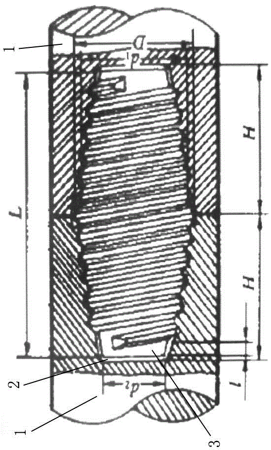
[0018] An electrode for LF refining furnace, as shown in the figure, it includes an electrode body 1 and an electrode joint 3 threadedly connected with it, the nominal diameter of the electrode body 1 is 450 mm, and the electrode joint 3 is a shuttle-shaped rotary body (that is, two ends The diameter is smaller than the diameter of the middle part, and its cross section is circular), the outer surface of the electrode joint 3 is provided with a connecting thread, one end of the electrode body 1 is provided with a joint hole 2 that matches the electrode joint 3, and the inner surface of the joint hole 2 The side is provided with an internal thread. In the electrode joint 3, the maximum diameter of the electrode joint 3 is divided into two sections in the axial direction, and the two sections of the electrode joint 3 are respectively matched with the joint holes 2 of the two adjacent electrode bodies 1, so as to realize the electrode joint 3 Two adjacent electrode bodies 1 are c...

Embodiment 2

[0022] The difference between this embodiment and Embodiment 1 is that the maximum inner diameter D of the joint hole 2 ranges from 273 to 274 mm, and the diameter of one end of the electrode joint 3 is d 1 The range of value is 264~265mm, the diameter of the other end of the electrode connector 3 is d 2 The value range of the length L of the electrode joint 3 is 198-199 mm, and the value range of the length L of the electrode joint 3 is 355-356 mm.

[0023] The electrode joint 3 of this structure can effectively improve its anti-breaking ability, and the electrode joint 3 will break once every five years on average. Compared with the prior art, the fracture frequency of the electrode joint 3 is reduced, thereby ensuring the smooth progress of production. Production costs are also reduced.

Embodiment 3

[0025] The difference between this embodiment and Embodiment 1 is that the maximum inner diameter D of the joint hole 2 is 273.05mm, and the diameter of one end of the electrode joint 3 is d 1 =264.62mm, the diameter of the other end of the electrode joint 3 is d 2 =198.70mm, the length L of the electrode joint 3=355.60mm.

[0026] The electrode joint 3 of this structure effectively improves its anti-breakability, and the electrode joint 3 has not broken after eight years of trial use, thereby ensuring smooth production and reducing production costs.


PUM

PropertyMeasurementUnit
diameteraaaaaaaaaa
lengthaaaaaaaaaa

Abstract

The invention provides an electrode for LF (ladle furnace) refining furnaces, which comprises an electrode body and an electrode contact connected with the electrode body through screws, wherein the electrode contact is a shuttle-shaped revolving body; the outer side surface of the electrode contact is provided with a connecting thread; one end of the electrode body is provided with a contact hole matched with the electrode contact; and the inner side surface of the contact hole is provided with an internal thread. After adopting the structure, the two adjacent electrode bodies can be conveniently connected together through the electrode contact, and the thread connection structure is convenient to disassemble and assemble and easy to implement. The maximal internal diameter of the contact hole is D which ranges from 270nm to 276nm, the diameter of one end of the electrode contact is d1 which ranges from 260nm to 268nm, the diameter of the other end is d2 which ranges from 195nm to 200nm, and the length of the electrode contact is L which ranges from 350nm to 360nm. The structural form effectively enhances the breaking resistance of the electrode contact, and prolongs the service life of the electrode contact.

Description

technical field [0001] The invention relates to an LF refining furnace, in particular to an electrode for the LF refining furnace. Background technique [0002] LF refining furnace is the necessary refining equipment for the current steel industry to enhance its own industry competitiveness and smelt high value-added products. It is also the necessary production equipment for all steel mills to coordinate production rhythm and save accidents. It has become the mainstream refining configuration of major steel mills. . However, with the rapid development of LF refining furnace technology, some defects of LF refining furnace itself are gradually exposed, and with the different operating conditions of each steel plant, the problems exposed by LF ladle refining furnace are also different. The most common It is the problem of electrode breakage, especially the problem of electrode joint breakage. Since the electrode joint bears the largest force, the electrode joint is the weak l...

Claims


Application Information

Patent Timeline
Patent Type & Authority Applications(China)
IPC IPC(8): C21C7/00
Inventor 李君彦胡勤东尚玉民牛宏波梁亚
Owner JIGANG GRP
Learn More