
Pipeline liquid exhaust device for flow testing

A technology of flow test and exhaust device, applied in the direction of measurement device, liquid/fluid solid measurement, measurement capacity, etc., can solve the problems of inconvenient installation and repair, inability to meet the requirements of gas elimination, top bending of float lever, etc., and achieve the installation pendulum. The effect of stable placement, convenient connection and convenient maintenance

Inactive Publication Date: 2014-09-03
HUNAN XD HEAVY EQUIP
View PDF6 Cites 2 Cited by
  • Summary
  • Abstract
  • Description
  • Claims
  • Application Information

AI Technical Summary

Problems solved by technology

[0003] At present, the known manual or automatic exhaust tanks or degassing filters on the market are generally used in steady-state liquid pipelines, and can only eliminate a small amount of air bubbles. The condition of air bubbles cannot meet its degassing requirements at all
Moreover, these known exhaust tanks or air getter transitions generally adopt the method of liquid filtration and then through the float type exhaust. Unreliable, inconvenient installation and repair, high investment costs, etc., and there is no exhaust tank or air filter that can intuitively know whether the liquid level in the tank can really maintain stability during its working process and see the effect of air elimination

Method used


Image

  • Pipeline liquid exhaust device for flow testing
  • Pipeline liquid exhaust device for flow testing
  • Pipeline liquid exhaust device for flow testing

Examples


Embodiment Construction

[0023] The present invention will be further described below in conjunction with the accompanying drawings and embodiments.

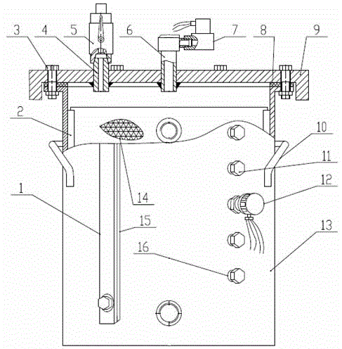
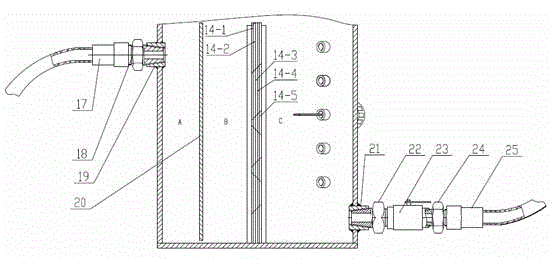
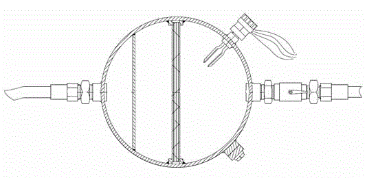
[0024]Referring to the accompanying drawings, this embodiment includes a welded barrel-shaped tank body 13, said tank body 13 is assembled and connected with the top cover 9 through 8 bolt assemblies 3 and a 3mm thick annular oil-resistant rubber sealing backing plate 8, forming a realizable Oil and air-tight container space; the tank body 13 is provided with an inlet screw seat 19 and an outlet screw seat 21, the inlet screw seat 19 and the outlet screw seat 21 are located on the same plane passing through the central axis, and the inlet screw seat The position of 19 is higher than the position of the outlet screw seat 21. The outlet screw seat 21 is vertically welded with a liquid level gauge mounting seat 15 at 45° to the left of the center of the circle. The liquid level gauge mounting seat 15 is equipped with a scale The liquid level gauge 1, the o...


PUM


Abstract

The invention relates to a pipeline liquid exhaust device for flow testing. The pipeline liquid exhaust device comprises a tank body, wherein an inlet screw base, an outlet screw base, a liquidometer mounting base and a liquidometer, as well as a tuning-fork-type material level limiting switch mounting screw base and a tuning-fork-type material level limiting switch which are arranged on the tank body; a filter screen mounting guide groove is formed in the tank body in a welding manner, and a filter screen is inserted into the filter screen mounting guide groove; a clapboard is welded between the filter screen and the inlet screw base which are arranged in the tank body, and the clapboard is welded with the inner wall of the tank body; an electromagnetic valve mounting connector assembly and a manual exhaust valve mounting connector are welded on a top cover; the electromagnetic mounting connector assembly is connected with an electromagnetic valve; a manual cutoff ball valve I is arranged on the manual exhaust valve mounting connector; the inlet screw base is connected with a transitional connector I and a transparent hose I; the outlet screw base is connected with a transitional connector II, a manual cutoff ball valve II, a transitional connector III and a transparent hose II. The pipeline liquid exhaust device disclosed by the invention can be used for exhausting of an oil return pipeline of a heavy-duty dump truck engine which runs under a harsh working condition in a mine, and can achieve an effect of completely eliminating a great amount of bubbles continuously generated in a liquid in the pipeline.

Description

technical field [0001] The invention relates to an exhaust device, in particular to a pipeline liquid exhaust device for flow testing. Background technique [0002] As we all know, whether it is liquid manufacturing industries such as petrochemical industry or automobile and automobile engine manufacturing industries, the measurement of fluid flow is measured by flowmeters. Most of the measured liquids contain various gases to varying degrees. If these gases Infiltrating and dissolving into the liquid medium, so that the state of gas-liquid two-phase coexistence enters the flowmeter, which will not only affect the measurement accuracy of the flowmeter, but also affect the service life of the flowmeter. As far as the on-road and off-highway automobile manufacturing industry is concerned, fuel consumption is an economic evaluation index that manufacturers and users are very concerned about, especially for off-highway heavy-duty dump trucks (electric transmission or mechanical ...

Claims


Application Information

Patent Timeline
IPC IPC(8): G01F15/08
Inventor 文炳培刘建坤钟家衡晏喜唐晟
Owner HUNAN XD HEAVY EQUIP
Learn More