Permanent magnet DC linear flexible drive

A flexible driver and permanent magnet technology, applied in the direction of electrical components, electromechanical devices, etc., can solve the problems of good motion controllability, small mass and volume, and good motion flexibility, and achieve simple process, small overall volume, and good motion flexibility Effect

Inactive Publication Date: 2016-06-01
HEFEI UNIV OF TECH
View PDF3 Cites 0 Cited by
  • Summary
  • Abstract
  • Description
  • Claims
  • Application Information

AI Technical Summary

Problems solved by technology

[0005] It can be seen from Table 1 that the existing linear actuators cannot simultaneously meet the characteristics of small mass and volume, good motion flexibility, no force fluctuation, good motion controllability, and large output force.

Method used


Image

  • Permanent magnet DC linear flexible drive
  • Permanent magnet DC linear flexible drive
  • Permanent magnet DC linear flexible drive

Examples


Embodiment Construction

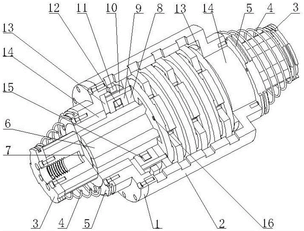
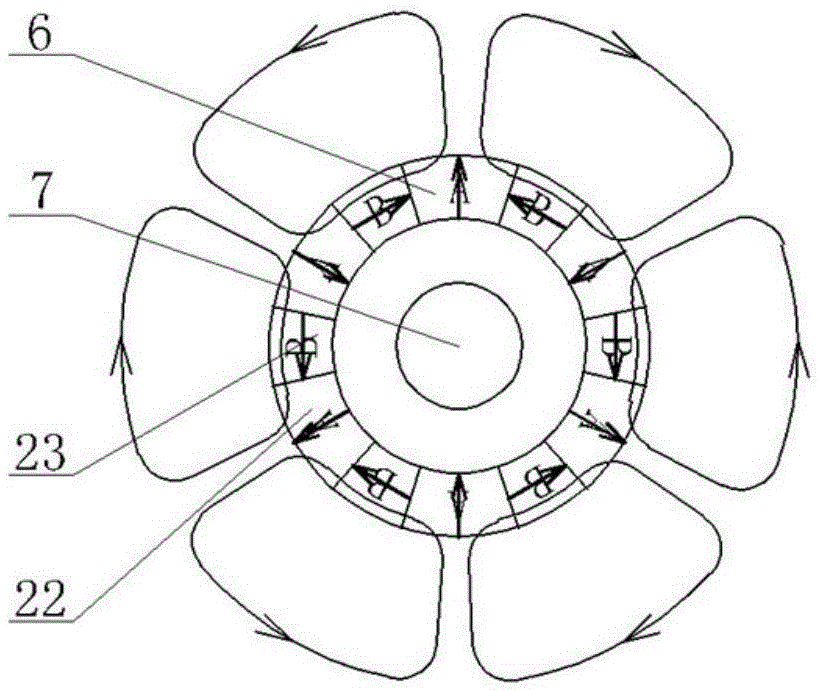
[0035] see figure 1 , Figure 6a and Figure 6b , the structural form of the permanent magnet DC linear flexible driver in this embodiment is:

[0036] The mover is composed of a magnetic steel support shaft 7 and a magnetic steel 6 fixedly sleeved on the magnetic steel support shaft 7. The magnetic steel 6 is bonded to the magnetic steel support shaft 7 with superglue, and its structure is simple. The two ends are respectively provided with mover end covers 3; the stator in the form of a cylinder is composed of the stator yoke 9, the stator winding 11, the winding wedge 12, the positioning rod 10 and the positioning ring 8; 1 and the housing 2 constitute a cylindrical shell, and support end caps 5 are respectively provided at both ends of the cylindrical shell; a buffer spring 4 is arranged between the support end cap 5 and the mover end cap 3 to form a buffer limit structure, which plays a role in The function of buffer protection and limit position; the linear bearing 14...


PUM


Abstract

The invention discloses a permanent magnet direct current linear flexible driver. The permanent magnet direct current linear flexible driver is characterized in that a rotor is formed by a magnetic steel supporting shaft and magnetic steel fixedly arranged on the magnetic steel supporting shaft in a sleeved mode, and the two ends of the rotor are provided with rotor end covers respectively; a cylinder-shaped stator is formed by a stator yoke, a stator winding, a winding wedge, a positioning rod and a positioning ring; the outer portion of the cylinder-shaped stator is provided with a cylindrical outer shell composed of an outer shell end cover and a shell, and the two ends of the cylindrical outer shell are provided with supporting end covers respectively; buffering springs are arranged between the supporting end covers and the rotor end covers to form a buffering limiting structure; linear bearings coaxially arranged with the stator and the cylindrical outer shell are fixedly arranged at the two ends of the cylindrical outer shell in an interference fit mode, and the rotor can do reciprocating movement in the linear bearings in the axial direction. The permanent magnet direct current linear flexible driver is light, small in size, good in controllability, free of fluctuation in output force, large in density of output force and very good in compatibility, and has driving flexibility and moving flexibility.

Description

technical field [0001] The invention relates to an electromagnetic linear flexible driving device, in particular to a device used in an automatic control system as a linear driver for realizing linear motion. Background technique [0002] The linear actuators used to realize linear motion in the prior art mainly include: electromagnetic relays, linear motors, linear push rods, hydraulic cylinders, pneumatic cylinders, pneumatic artificial muscles, and some new functional materials. Among them, the electromagnetic relay uses the electromagnetic force generated by the electromagnet composed of the energized solenoid and the iron core and its own elastic element to realize the linear contraction and recovery of the armature; the linear motor uses the principle of electromagnetic induction to directly convert electric energy into linear motion Mechanical energy does not require any intermediate conversion mechanism; the linear push rod is an electric drive device that converts t...

Claims


Application Information

Patent Timeline
Patent Type & Authority Patents(China)
IPC IPC(8): H02K33/18
Inventor 胡小春夏勤陈甦欣许程鹏杨飞飞
Owner HEFEI UNIV OF TECH
Why Eureka
Try Eureka