Stator core manufacturing method and stator core

The technology of a stator iron core and manufacturing method is applied in the direction of manufacturing motor generators, shape/style/structure of winding insulation, magnetic circuit shape/style/structure, etc., and can solve problems such as thickness deviation and thickness deviation of iron core 54, To achieve the effect of preventing burrs

Active Publication Date: 2014-09-03
MITSUBISHI ELECTRIC CORP
View PDF6 Cites 5 Cited by
  • Summary
  • Abstract
  • Description
  • Claims
  • Application Information

AI Technical Summary

Problems solved by technology

[0011] At this time, since the thickness of each core piece 54 varies, the thickness of each core block main body 51 along the stacking direction of the core pieces 54 varies.

Method used


Image

  • Stator core manufacturing method and stator core
  • Stator core manufacturing method and stator core
  • Stator core manufacturing method and stator core

Examples


Embodiment Construction

[0040] Hereinafter, the best mode for carrying out the present invention will be described with reference to the drawings.

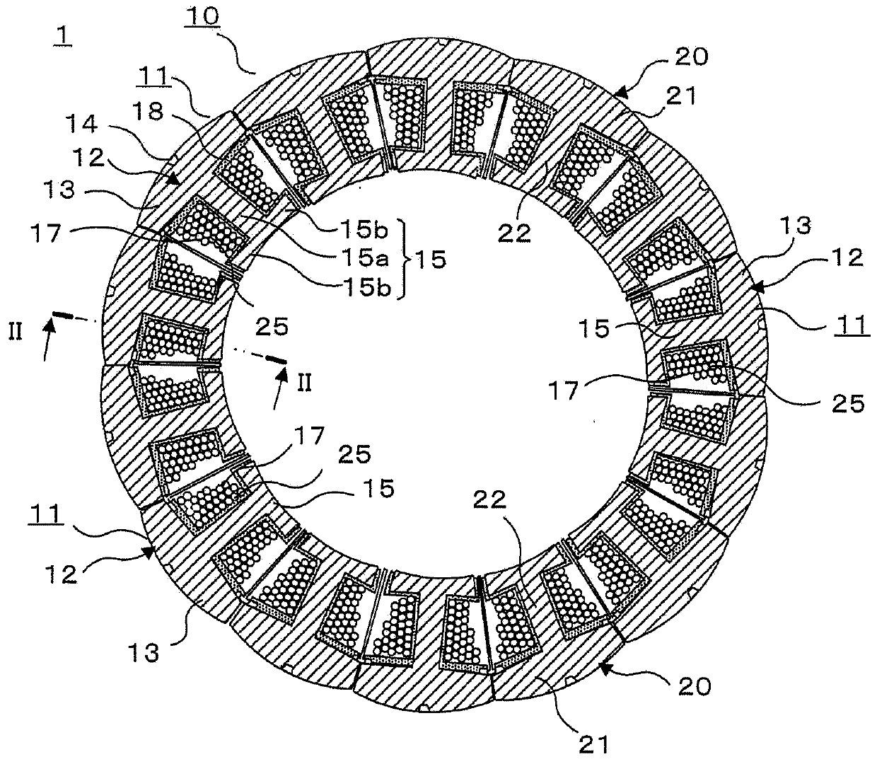
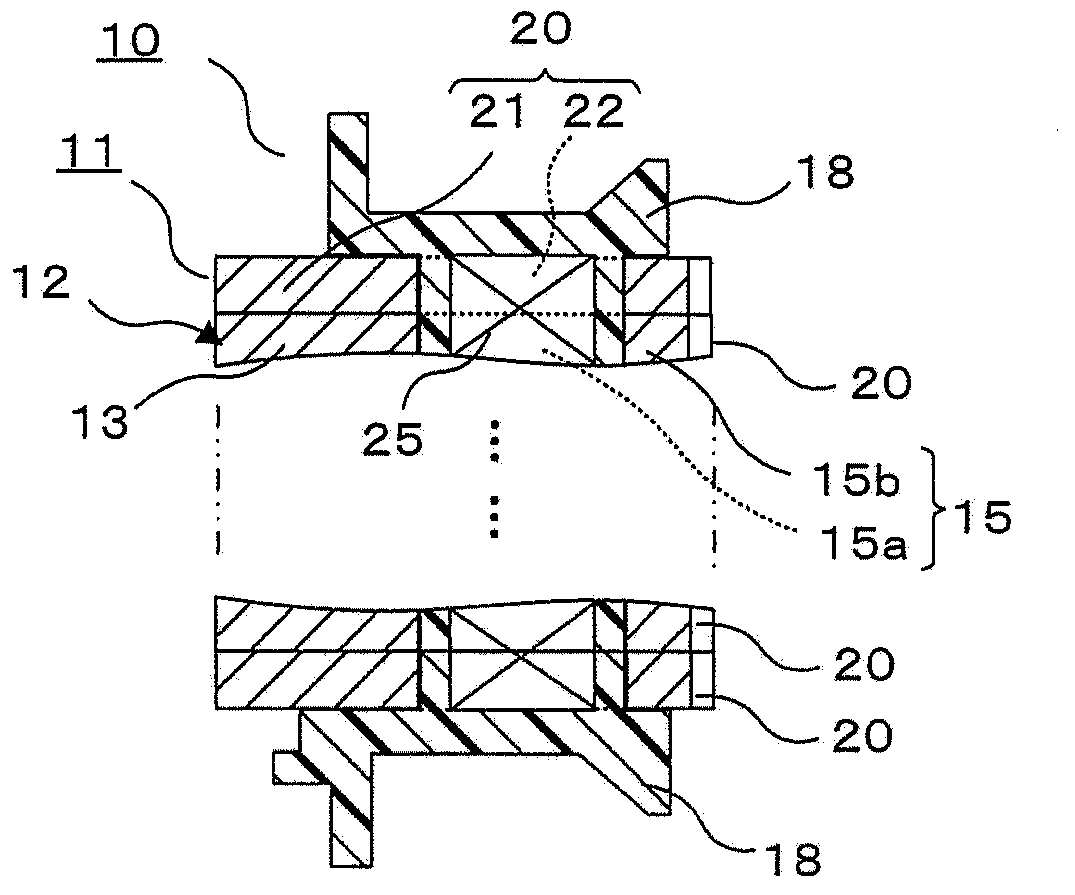
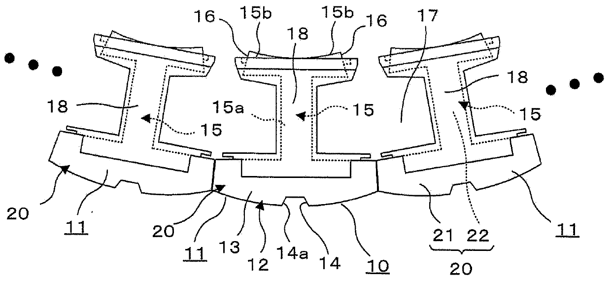
[0041] figure 1 is a cross-sectional view perpendicular to the axial direction of a stator having a stator core manufactured by a stator core manufacturing method according to an embodiment of the present invention, figure 2 is along figure 1 The sectional view of the main part observed by the II-II arrow, image 3 It is a plan view seen from the axial direction of the stator core manufactured by the manufacturing method of the stator core which concerns on one Embodiment of this invention.

[0042] exist Figure 1 ~ Figure 3 Among them, the stator 1 includes: an annular stator core 10 ; and a stator winding 25 provided on the stator core 10 so as to be spaced apart from each other along the circumferential direction of the stator core 10 .

[0043] The stator core 10 is composed of a plurality of core blocks 11 connected in a ring shape.

[0044...


PUM


Abstract

In order to prevent unwanted burr formation on an insulating resin that is provided between a stator winding and a main core block body, the present invention provides a stator core manufacturing method for manufacturing a stator core that is constructed by connecting, into a circular shape, multiple core blocks (11), each being constructed by laminating multiple core pieces (20) together in the axial direction, wherein each core block (11) is equipped with a main core block body (12) that has a yoke section (13) and a magnetic pole tooth section (15), and an insulating resin layer (18) that is provided between a stator winding (25) and the main core block body (12) so as to cover a section that includes the surface of the magnetic pole tooth section (15) around which the stator winding (25) is wound. The stator core manufacturing method includes an injection molding step in which the insulating resin layer (18) is integrally formed with the main core block body (12) for each main core block body (12) by means of injection molding.

Description

technical field [0001] The present invention relates to a stator core manufacturing method and a stator core for manufacturing stator cores used in motors and generators such as automobiles, for example. Background technique [0002] A stator constituting a general electric motor or generator mounted on an automobile or the like includes a stator core and a stator coil wound around the stator core. [0003] The stator core includes: a core body having an annular yoke body and a plurality of magnetic pole teeth protruding radially inward from the inner peripheral surface of the yoke body at intervals from each other in the circumferential direction; and an insulating member covering the main part of the core body including the surface of the pole teeth on which the stator winding is wound, the insulating member being interposed between the stator winding and the main part of the core body. [0004] Conventionally, as an insulating member, an insulating film or the like provi...

Claims


Application Information

Patent Timeline
IPC IPC(8): H02K15/12H02K1/14H02K3/34
CPCH02K15/12H02K2203/12H02K3/522H02K1/148
Inventor 广田穰胁田觉司朴和彦桥本昭鹈饲义一
Owner MITSUBISHI ELECTRIC CORP
Why Eureka
Try Eureka