Driver circuit for at least one load and method of operating the same

A driver circuit and circuit technology, applied in the power supply field, can solve the problems of complexity, high cost, unsuitable for large-scale market application, etc., and achieve the effect of improved control and high-quality light output

Active Publication Date: 2014-09-03
SIGNIFY HLDG BV
View PDF3 Cites 12 Cited by
  • Summary
  • Abstract
  • Description
  • Claims
  • Application Information

AI Technical Summary

Problems solved by technology

[0005] However, currently available solutions often include complex and thus costly circuits, which are not suitable for mass market applications

Method used


Image

  • Driver circuit for at least one load and method of operating the same
  • Driver circuit for at least one load and method of operating the same

Examples


Embodiment Construction

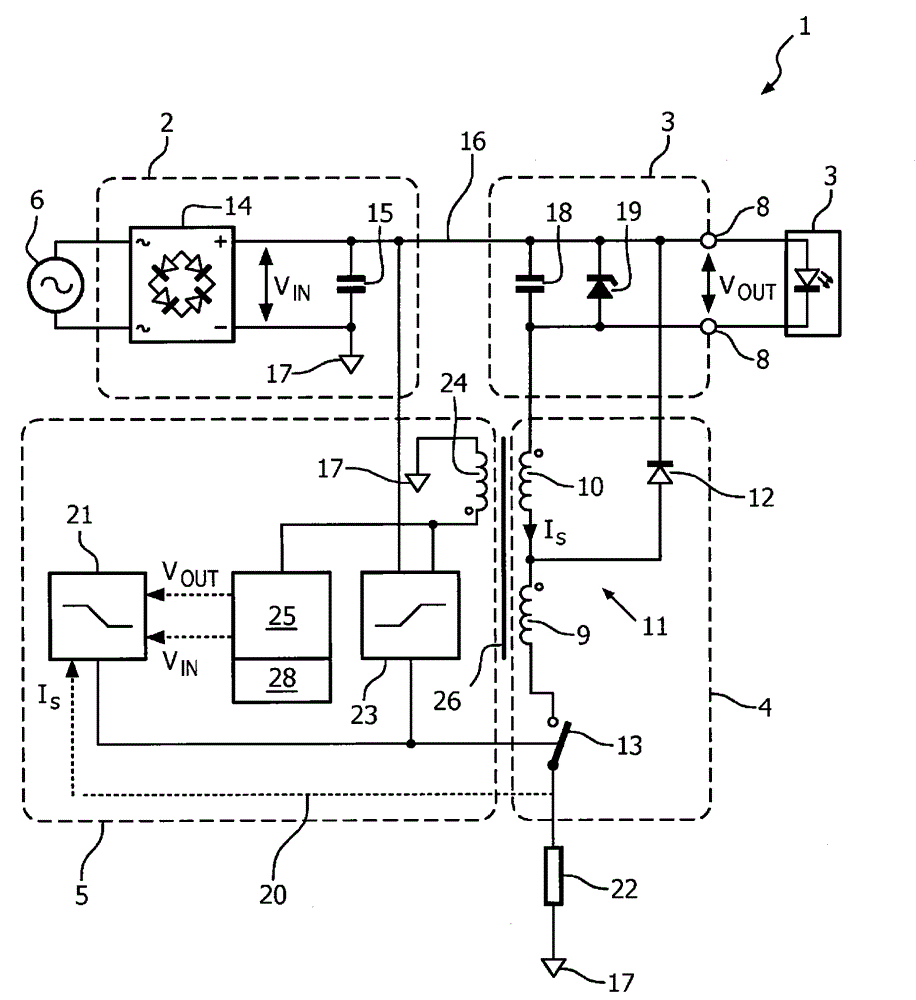
[0072] figure 1 A schematic block diagram of a driver circuit 1 according to the invention is shown. The driver circuit 1 includes an input 2 , an output 3 , a switching converter 4 and a switching controller 5 . The input 2 is connected to a power supply 6, which according to the example is a 220V or 110V mains line and is configured to provide the driver circuit 1 with an input voltage V IN . The output 3 is connected to the LED unit 7 via an output terminal 8 which may form a separable connector. The LED unit 7 according to this example comprises a plurality of high power LEDs (not shown) connected in series, which results in an output voltage V corresponding to the overall forward voltage of the LEDs. OUT .

[0073] according to figure 1 The driver circuit 1 is configured to provide operating current to the LED unit 7 from the mains power supply 6 . Since typical LEDs are driven with a voltage substantially lower than the mains voltage, the arrangement of the driver ...


PUM


Abstract

A driver circuit (1) for operating at least one load, such as a LED unit (7) is provided, comprising an input (2) for receiving an input voltage (V IN ) from a power supply (6), an output (3) for providing an output voltage (V OUT ) to said load and a switching converter (4) with at least a storage inductor (11) connected with a switching device (13), said switching converter (4) being disposed to generate an average output current by sequential switching operation of said switching device (13) between at least a charging mode and a discharging mode. Furthermore, a switching controller (5) is connected with said switching device (13) to control the switching operation of said switching device (13) and comprises a feedback inductor (24), inductively coupled to said storage inductor (11) to provide a feedback voltage, corresponding to the variation of an inductor current (I S ) through said storage inductor (11) and a voltage compensation circuit (25), connected with said feedback inductor (24) to determine at least one compensation signal from said feedback voltage, said compensation signal corresponding to said input voltage (V IN ) or said output voltage (V OUT ). To provide a cost-efficient and versatile driver circuit (1), the switching controller (5) is configured to at least control said switching device (13) between said discharging and said charging mode in dependence on said inductor current (I s ) and to control a duty cycle of the switching operation in dependence on said at least one compensation signal, so that in case of a variation of said input (V IN ) or output voltage (V OUT ), said average output current, provided to the load, is maintained substantially constant.

Description

technical field [0001] The present invention relates to the field of power supplies and in particular to a driver circuit for at least a load such as an LED unit and a method of operating the same. Background technique [0002] In the field of lighting, current R&D is focused on reducing power consumption for everyday lighting. Light emitting diodes (LEDs) have become an alternative to conventional incandescent or halogen lamps for general room lighting applications such as in residential or commercial environments. In addition to reduced power consumption, LEDs further offer the advantage of a significantly increased lifetime, which reduces installation and replacement costs. [0003] When light sources comprising LEDs or similar devices are employed, it is generally necessary to provide a constant current to one or more LEDs because the current through the LEDs varies exponentially with the applied voltage. Without proper circuitry, voltage variations can easily cause ex...

Claims


Application Information

Patent Timeline
Patent Type & Authority Applications(China)
IPC IPC(8): H05B33/08H05B44/00
Inventor 赖兵
Owner SIGNIFY HLDG BV
Why Eureka
Try Eureka