Tape feeder

A belt feeder, the technology of the belt feeder

Active Publication Date: 2014-09-03
FUJI KK
View PDF5 Cites 7 Cited by
  • Summary
  • Abstract
  • Description
  • Claims
  • Application Information

AI Technical Summary

Problems solved by technology

[0005] In the above-mentioned conventional tape feeder, the operator installs the component supply tape on the tape feeder and engages the teeth of the toothed reel with the toothed reel holes of the component supply tape pulled out from the tape reel. complicated

Method used


Image

  • Tape feeder
  • Tape feeder
  • Tape feeder

Examples


Embodiment Construction

[0036] Hereinafter, one Example of the specific form for implementing this invention is demonstrated using drawing.

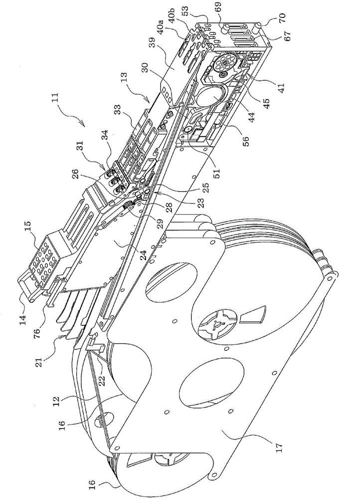
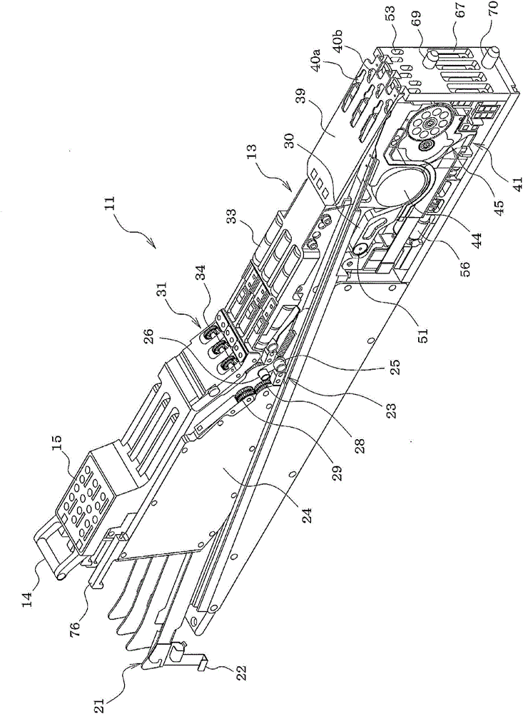
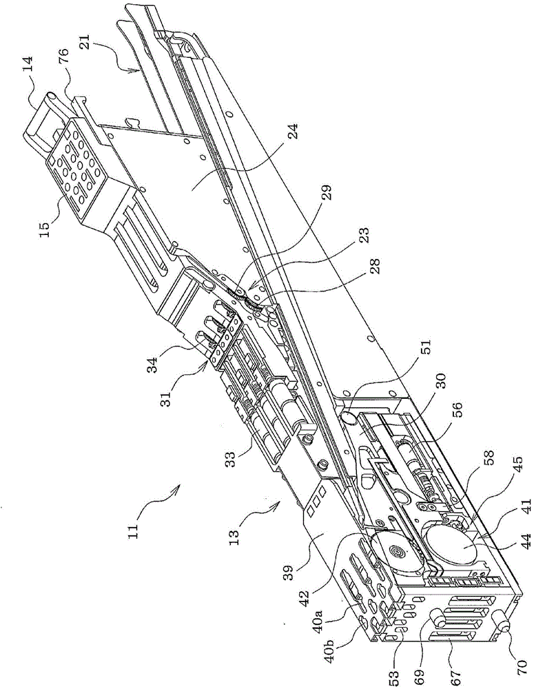
[0037] First, the structure of the tape feeder 11 is demonstrated.

[0038]In the tape feeder 11, the width of the feeder main body 13 is approximately the same as that of a conventional general tape feeder (only the multiples of the width of a tape feeder for a component supply tape. In the present embodiment, the width of the feeder main body 13 is made, for example, approximately four times (approximately M times) the width of the conventional general tape feeder by reducing the interval between the adjacent component supply tapes 12 . It is possible to arrange six (N, where N is an integer larger than M) component supply belts 12 in the width direction. Although not shown in detail, the component supply tape 12 accommodates components in component accommodating recesses formed in a line at a predetermined pitch in a carrier tape, and a top tape (also call...


PUM


Abstract

When setting component supply tape 12 on feeder main body 13, after sprocket 42 (sprocket moving mechanism 45) is automatically lowered to the retract position and component supply tape 12 is set above sprocket 42, control is performed to raise sprocket 42 to the engagement position; if control is performed to raise sprocket 42 to the engagement position but the teeth of sprocket 42 do not engage with the sprocket holes of component supply tape 12 and a detection signal is not output from engagement detection sensor 63, rotation of sprocket 42 via automatic engagement operation is performed whereby sprocket 42 is rotated by motor 44 until the teeth of sprocket 42 engage with the sprocket holes of component supply tape 12 and a detection signal is outputted by engagement detection sensor 63.

Description

technical field [0001] The present invention relates to a tape feeder having an improved structure for providing a component supply tape in which a plurality of components are arranged at predetermined intervals. Background technique [0002] A general tape feeder is described in Patent Document 1 (Japanese Patent Laid-Open No. 2010-109109 ), in which the teeth of the toothed reel and the toothed roll formed at a constant pitch along the side edge of the component supply tape While the reel holes are engaged, the component supply tape is fed by the rotation of the toothed reel to the component suction position, where the components of the component supply tape are sucked by the suction nozzle of the component mounting machine. [0003] The operation of setting the component supply tape on this tape feeder is performed by removing the tape feeder from the component mounting machine, setting the reel of the component supply tape on the tape feeder, and making the The teeth me...

Claims


Application Information

Patent Timeline
Patent Type & Authority Applications(China)
IPC IPC(8): H05K13/02
CPCH05K13/0417H05K13/0419
Inventor 高田幸则
Owner FUJI KK
Why Eureka
Try Eureka