Swing bridge for converting a rotary motion into an oscillating motion

A technology of rotary motion and oscillating motion, which is applied in metal processing and other directions, can solve problems such as increased noise level, collision between drive device and vibration bridge, and achieves the effects of reduced complexity, optimized service life, and good manufacturing tolerances

Inactive Publication Date: 2014-09-10
BRAUN AG
View PDF6 Cites 1 Cited by
  • Summary
  • Abstract
  • Description
  • Claims
  • Application Information

AI Technical Summary

Problems solved by technology

In other words, an increase in the manufacturing tolerances in the area of ​​the coupling will directly lead to an increase in the noise level, since every time the vibrating bridge changes direction, every play in this area must be reabsorbed and thus eventually drive Constant impact of the device onto the vibrating bridge

Method used


Image

  • Swing bridge for converting a rotary motion into an oscillating motion
  • Swing bridge for converting a rotary motion into an oscillating motion
  • Swing bridge for converting a rotary motion into an oscillating motion

Examples


Embodiment Construction

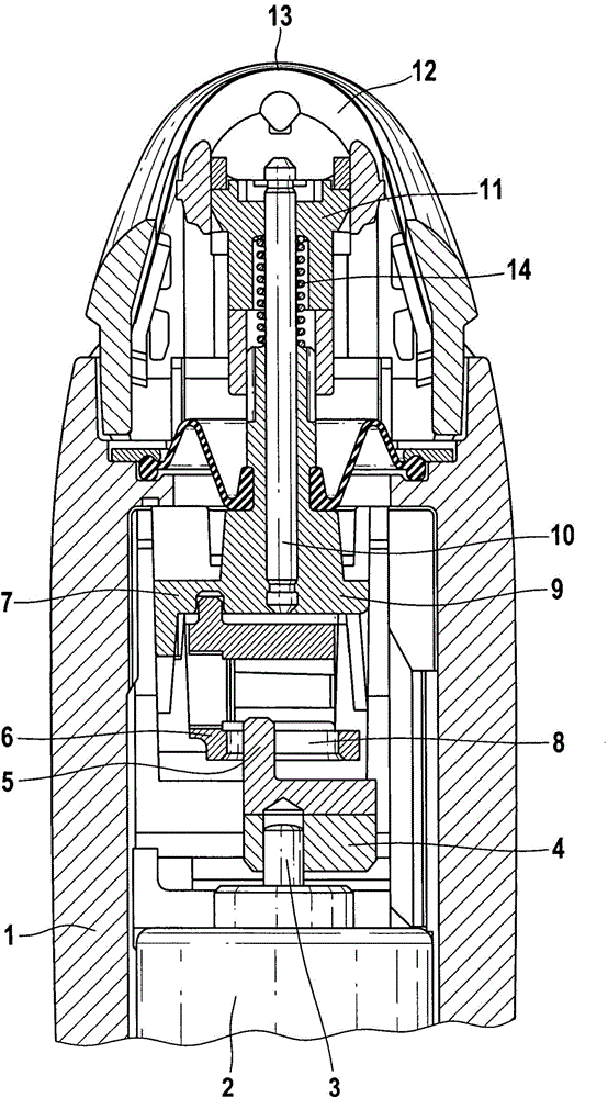
[0016] exist figure 1 The dry shaving apparatus shown in has a housing 1 in which an electric motor 2 with a drive shaft 3 is fastened. Mounted on the drive shaft 3 is an eccentric part 4 , which is connected to the drive shaft 3 in a rotationally fixed and at the same time fixed manner in the axial direction. The eccentric part 4 has a pin 5 offset eccentrically relative to the drive shaft 3 , which engages in a coupling part 6 of a vibrating bridge 7 . For this purpose, the coupling part 6 has an opening 8 extending horizontally in the plane of the drawing, the width of which corresponds to the diameter of the pin 5 .

[0017] As soon as the drive shaft 3 of the electric motor 2 is driven in rotation, an oscillating movement is produced by the vibrating bridge, the direction of which is perpendicular to the plane of the drawing. The oscillating body 9 is provided in its upper region with a bearing pin on which the lower knife 11 of the shearing system is held. In a known ...


PUM


Abstract

The invention relates to a swing bridge for converting a rotary motion into an oscillating motion in an electrical device. The housing (1) of the electrical device holds a drive mechanism (2) that is powered by rotation with a drive shaft (3) and that has a crank or cam-type section (4) and at least one coupling element (15) of the swing bridge (7). The swing bridge (7) has at least one swing arm (16) by means of which the coupling point (15) is elastically connected to the oscillating body (9). The oscillating body (9) carries a working medium (11) to be powered by oscillations and has a coupling (6) for the crank or cam-type section (4) of the drive shaft (3). The coupling (6) is formed as a separate component which is connected to the oscillating body (9).

Description

[0001] The application date is April 7, 2007, the date of entering China's national phase is November 17, 2008, the national application number is 200780018001.7 and the invention name is "A vibrating bridge for converting rotational motion into oscillating motion and the A divisional application of the PCT invention patent application for the application of vibration bridges in electrical equipment. technical field [0002] The invention relates to a vibrating bridge for converting a rotational movement into an oscillating movement in an electrical device according to the preamble of claim 1 . Background technique [0003] Such a vibrating bridge is known, for example, from DE 32 24 223 C2 and is also used in electric dry shaving devices. For noise-optimized and weight-optimized reasons, vibration bridges of this type are usually produced from plastic in small electrical appliances, and moreover they are usually designed in one piece. In principle, different synthetic mate...

Claims


Application Information

Patent Timeline
Patent Type & Authority Applications(China)
IPC IPC(8): B26B19/28
CPCB26B19/28
Inventor 丹尼尔·迪策尔马蒂亚斯·韦策尔诺贝特·克罗伊茨福尔克尔·施滕格尤尔根·霍泽
Owner BRAUN AG
Why Eureka
Try Eureka