Cabinet door lock and lock mechanism in cabinet door lock

A technology of locking mechanism and cabinet door, which is applied to non-mechanical transmission-operated locks, building locks, door/window accessories, etc., can solve problems such as insecurity, and achieve the effect of simple and compact structure, ingenious setting, stable, reliable and smooth movement.

Active Publication Date: 2014-09-10
JIANGSU YINHE ELECTRONICS
View PDF4 Cites 5 Cited by
  • Summary
  • Abstract
  • Description
  • Claims
  • Application Information

AI Technical Summary

Problems solved by technology

In practical applications, for some special-purpose cabinets for storing firearms, it is not safe for one person to control the switch of the cabinet. Usually, two people are required to restrain each other, jointly control or automatically control through a computer.

Method used


Image

  • Cabinet door lock and lock mechanism in cabinet door lock
  • Cabinet door lock and lock mechanism in cabinet door lock
  • Cabinet door lock and lock mechanism in cabinet door lock

Examples


Embodiment Construction

[0020] Specific embodiments of the present invention will be described in detail below in conjunction with the accompanying drawings.

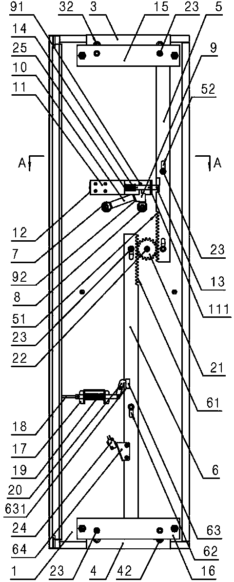
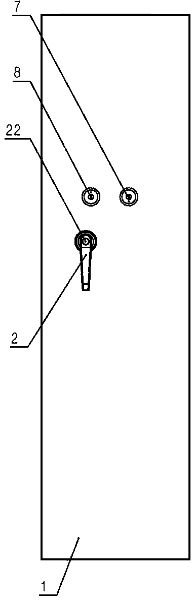
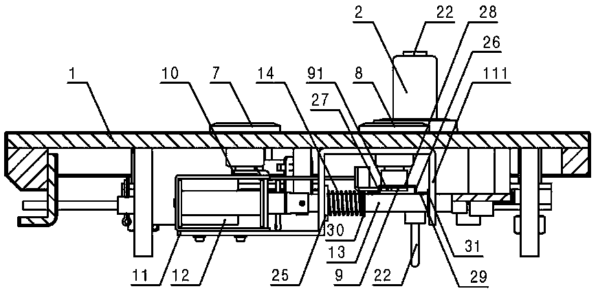
[0021] Such as figure 1 As shown, a cabinet door lock according to the present invention includes: a handle 2 that is movable through the middle part of the cabinet door 1—see figure 2 As shown, the handle 2 includes a handle for holding and a rotating shaft for turning. The upper and lower ends of the back of the cabinet door 1 are respectively provided with upper and lower door gates 3 and 4 through the gate guide positioning mechanism. The setting method of the gate guide and positioning mechanism is: a pair of guide holes 32 and 42 are respectively provided on the upper and lower gate gates 3 and 4 along the respective length directions, that is, a pair of guide holes 32 are provided on the upper gate gate 3, and a pair of guide holes 32 are provided on the lower gate gate 3. A pair of guide holes 42 are provided on the gate 4, and locki...


PUM


Abstract

The invention discloses a lock mechanism in a cabinet door lock, which is simple and compact in structure and capable of realizing two-person control and automatic computer control. The lock mechanism comprises a locking lever, wherein a driving lock control device, a driven lock control device and a locking horizontal-sliding seat are arranged on the cabinet door; a locking horizontal-sliding driving device is arranged on the locking horizontal-sliding seat; the locking lever is connected with the locking horizontal-sliding driving device; a locking reset spring is arranged between the locking lever and the locking horizontal-sliding seat; the driven lock control device comprises a controlled lock arranged in the cabinet door in a penetrating manner; a toggle sheet is arranged on a lock cylinder of the controlled lock; an unlocking bumping sheet and a locking bumping sheet which are matched with the toggle sheet are arranged on the locking lever; the toggle sheet is located between the unlocking bumping sheet and the locking bumping sheet; the driving lock control device comprises a master control lock arranged in the cabinet door in a penetrating manner; a locking plate for controlling the movement of the toggle sheet is arranged on the lock cylinder of the master control lock. The invention further discloses the cabinet door lock using the lock mechanism, which is suitable for a special cabinet with higher safety requirement.

Description

technical field [0001] The invention relates to a door lock, in particular to a cabinet door lock and a locking mechanism therein. Background technique [0002] At present, various cabinets made of metal materials usually have a lock to control the switch of the cabinet door, and the switch of the cabinet door can only be controlled by a mechanical lock. In practical applications, for some special-purpose cabinets for storing firearms, it is not safe for one person to control the switch of the cabinet. Usually, two people are required to restrain each other, jointly control or automatically control through a computer. Contents of the invention [0003] The technical problem to be solved by the present invention is to provide a locking mechanism in a cabinet door lock that has a simple and compact structure and can realize two-person control and computer automatic control at the same time. [0004] In order to solve the above technical problems, the technical solution adop...

Claims


Application Information

Patent Timeline
Patent Type & Authority Applications(China)
IPC IPC(8): E05B65/52E05B63/14E05B15/00E05B17/22E05B47/06E05B17/00E05B3/00
Inventor 顾益丰吴建明陈明易
Owner JIANGSU YINHE ELECTRONICS
Why Eureka
Try Eureka