Clamp control device

A control device and fixture technology, applied in the direction of electrolysis process, electrolysis components, etc., can solve the problems of automatic opening and closing, etc., achieve the effect of reducing load, compact control device, and improving sensitivity

Active Publication Date: 2014-08-13
KUNSHAN DONGWEI MACHINERY CO LTD
View PDF6 Cites 2 Cited by
  • Summary
  • Abstract
  • Description
  • Claims
  • Application Information

AI Technical Summary

Problems solved by technology

[0008] Therefore, the technical problem to be solved by the present invention is to overcome the technical defect that the clamps used for clamping the lower side of the thin plate in the existing electroplating production line cannot be opened and closed in an automated manner, so as to provide a clamp that can be opened and closed in an automated manner. Control device for the underside gripper of the sheet metal

Method used


Image

  • Clamp control device
  • Clamp control device
  • Clamp control device

Examples


Embodiment 1

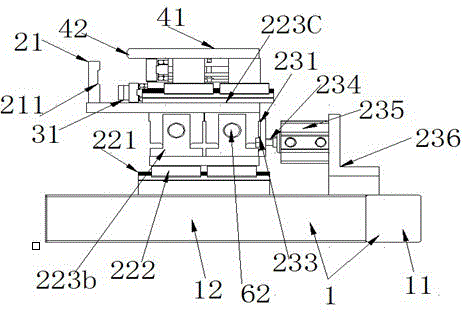
[0053] Such as figure 1 As shown, this embodiment provides a clamp control device, including a fixed bracket 1, the fixed bracket 1 includes a first fixed bracket 11 arranged along the running direction of the clamp, and vertically extending from the first fixed bracket 11 At least two second fixed mounts 12 and third fixed mounts 13 arranged at a certain distance, the first fixed mount 11, the second fixed mount 12 and the third fixed mount 13 are on the same height plane, and, The first fixing frame 11, the second fixing frame 12 and the third fixing frame 13 are all long slats, and the cooperation of the three forms the bottom supporting frame of the fixture control device of this embodiment. The supporting frame has the function of saving materials. specialty.

[0054] The core of this embodiment is that the gripper control device also includes a first movement device located on the fixed support 1, a second movement device, a third movement device arranged above the runn...

Embodiment 2

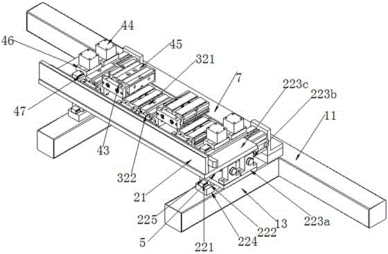
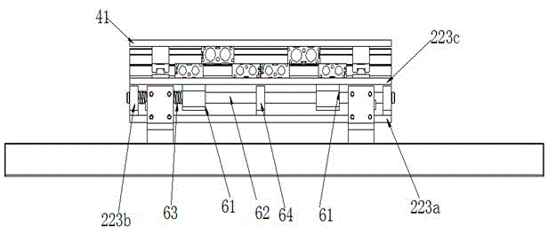
[0080] This embodiment provides a clamp control device, which is a modification based on Embodiment 1. In this embodiment, the telescopic device includes a device arranged between the first supporting plate 223a and the second supporting plate 223c and The slider fixed by the second support plate 223c is arranged on the track on the first support plate 223a, the slider is located in the track, and the first movement device, the second movement device or the third movement device are given to the clamp. When the driving force of the moving device is towards the front of the running direction, it can slide along the track with the slider to play the role of the above-mentioned elastic support member 63. When it needs to be reset, it can be reset by controlling the controller.


PUM

PropertyMeasurementUnit
thicknessaaaaaaaaaa

Abstract

The invention provides a clamp control device, comprising a fixed support and further comprising a first motion device arranged on the fixed support, a second motion device, a third motion device arranged above a running clamp and a telescopic device linked or reset with the first motion device or the second motion device or the third motion device along the running direction of the clamp, wherein an electric connector connected with a controller is arranged on the first motion device, the second motion device and the third motion device respectively, each electric connector can receive the motion time determined by the controller respectively, the first motion device and the second motion device produce opposite motions close to the running clamp or same motion away from the clamp at the motion time to clamp or release the clamp, and the third motion device directly applies a pressure to the clamp when the clamp is clamped, so that a mounting clearance is opened for clamping an electroplated plate in the clamp. Therefore, the automation degree is high.

Description

technical field [0001] The invention relates to a device for controlling a clamp for clamping a thin plate in an electroplating production line, and belongs to the technical field of electroplating plate clamping. Background technique [0002] During the electroplating process, it is often necessary to electroplate circuit boards of different thicknesses. Before electroplating, the circuit boards of different thicknesses need to be clamped by clamps to maintain the verticality of the circuit boards in the electroplating bath, thereby ensuring the quality of electroplating. [0003] For a circuit board with a large thickness, due to its high strength, it is only necessary to clamp the upper edge of the board through the upper clamp located above the board during the clamping process. During the transmission process of the board, the upper clamp and the board itself The combined effect of verticality enables the board to maintain good verticality. [0004] For thin plate elec...

Claims


Application Information

Patent Timeline
Patent Type & Authority Applications(China)
IPC IPC(8): C25D17/08
Inventor 江泽军
Owner KUNSHAN DONGWEI MACHINERY CO LTD
Why Eureka
Try Eureka