Large-scale multifunctional geosynthetic interface dynamic direct shear instrument

A geosynthetic, multi-functional technology, applied in the direction of testing the strength of materials by applying a stable shear force, can solve problems such as difficult research

Active Publication Date: 2016-04-06
TONGJI UNIV
View PDF6 Cites 0 Cited by
  • Summary
  • Abstract
  • Description
  • Claims
  • Application Information

AI Technical Summary

Problems solved by technology

Due to the lack of a direct shear device that can realize complex random vibration input, research in this area is difficult, and it is urgent to develop a geotechnical material interface dynamic direct shear device that can realize complex random vibration input

Method used


Image

  • Large-scale multifunctional geosynthetic interface dynamic direct shear instrument
  • Large-scale multifunctional geosynthetic interface dynamic direct shear instrument
  • Large-scale multifunctional geosynthetic interface dynamic direct shear instrument

Examples


Embodiment 1

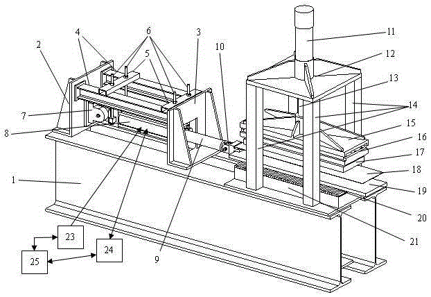
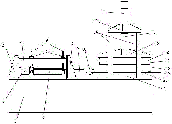
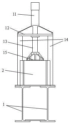
[0029] like Figure 1-Figure 7As shown, the device consists of the instrument base 1, the rear fixing bracket of the vibration exciter 2, the front fixing bracket of the vibration exciter 3, the longitudinal suspension beam 4, the horizontal suspension beam 5, the vibration exciter suspension fixing rod 6, and the vibration exciter fixing support 7 , Exciter cylinder 8, exciter dowel 9, connecting bayonet device 10, vertical press cylinder 11, fixed support top plate 12, vertical press dowel 13, vertical support column 14, loading plate 15. Consisting of lateral limit fixed frame 16, test soil sample 17, test geosynthetic material 18, dynamic extraction plate 19, steel rolling bar group 20, horizontal base 21, second layer test geosynthetic material 22, and vibration exciter Servo system 23, oil pressure delivery control system 24, computer adjustment control system 25. Among them, the instrument base 1 serves as the bottom fixing system of the whole multifunctional test plat...

Embodiment 2

[0035] The device described in Example 1 is used to test the double geosynthetic interface direct shear test mode, and its working process is as follows: a test geosynthetic material 18 with a size of 1250 mm × 350 mm is attached to the upper surface of the dynamic extraction plate 19, and the A test geosynthetic material with a size of 1050mm×350mm is attached to the lower surface of the pressure loading plate 15, and the computer numerical control system 31 and the oil pressure control system 30 are controlled to make the geosynthetic material 22 on the lower surface of the pressure loading plate 15 and the dynamic extraction plate 19 The geosynthetic material 18 on the surface contacts to form a shear plane, and the applied normal pressure continues to increase until it reaches the experimental set value. The extraction plate 19 and the exciter dowel 9 are firmly connected with bolts through the steel dowel fixing device 10, the computer numerical control system 25 and the o...


PUM

PropertyMeasurementUnit
lengthaaaaaaaaaa
lengthaaaaaaaaaa
lengthaaaaaaaaaa

Abstract

The invention belongs to the technical field of geotechnical engineering, and in particular relates to a large-scale multifunctional geosynthetic material interface dynamic direct shear instrument. It consists of base, front and rear fixing brackets, horizontal and vertical suspension beams, suspension rods, vibrator (oil cylinder, support, dowel bar, bayonet), vertical pressure device, top plate, support column, loading plate, side limit frame, test It is composed of soil sample and geosynthetic material, extraction plate, steel rolling bar group, horizontal base, servo system, hydraulic system and computer control system. The front and rear fixed brackets and suspension beams fix the exciter, the top plate, support columns and horizontal base form the frame and fix the vertical pressure device and loading plate, and the rest of the components form the shear box. The vibration of the exciter and the extraction plate is controlled by the computer control system and the oil pressure system, and the stress and strain indicators are monitored by the servo system. The invention can measure the dynamic shear characteristic of the geosynthetic material interface under the action of any vibration waveform, and the instrument can also test various interfaces by replacing parts, so as to realize other test purposes.

Description

technical field [0001] The invention belongs to the technical field of geotechnical engineering, and in particular relates to a large-scale multifunctional geotechnical synthetic material interface dynamic direct shear instrument, which can realize various geotechnical material interface dynamic direct shear tests. Background technique [0002] Geosynthetics are industrial products made of synthetic polymers (such as plastics, chemical fibers, synthetic rubber, etc.) Synthetic materials, geotechnical special materials and geocomposites, geonets, fiberglass mesh, geomats and other types. Geosynthetics are widely used as a liner system at the bottom of foundations of landfills and low buildings to isolate pollutants from leaking. When earthquake disasters occur, geosynthetics composite liner systems will play a complex role. the shock isolation effect. However, the shear strength of geosynthetics is generally low, and complex relative motions will occur along the interface o...

Claims


Application Information

Patent Timeline
Patent Type & Authority Patents(China)
IPC IPC(8): G01N3/24
Inventor 冯世进沈阳
Owner TONGJI UNIV
Why Eureka
Try Eureka