
Hardness tester rack device beneficial for measurement accuracy

A technology of measuring accuracy and hardness tester, applied in the direction of testing material hardness, etc., can solve the problems of affecting the perpendicularity of the strike pin and the material table, inconvenient precise control of the position accuracy of the Shore hardness tester, etc., to achieve simple structure, optimized measurement accuracy, convenient The effect of height adjustment

Active Publication Date: 2014-09-10
API ZC PRECISION INSTUMENT CO LTD
View PDF4 Cites 12 Cited by
  • Summary
  • Abstract
  • Description
  • Claims
  • Application Information

AI Technical Summary

Problems solved by technology

[0004] In order to solve the problem in the above-mentioned prior art that adjusting the clearance fit between the Shore hardness tester and the slide bar affects the perpendicularity between the striker pin and the material table, and at the same time the position accuracy of the Shore hardness tester on the slide bar is not easy to be accurately controlled, The invention provides a hardness tester bench device which is beneficial to the measurement accuracy

Method used


Image

  • Hardness tester rack device beneficial for measurement accuracy
  • Hardness tester rack device beneficial for measurement accuracy

Examples


Embodiment 1

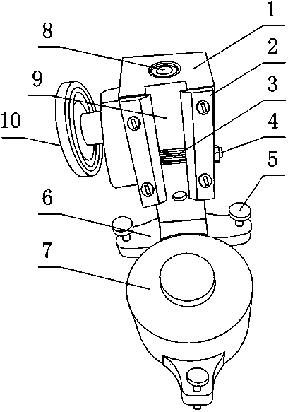
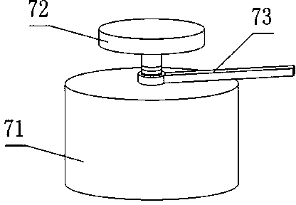
[0026] like figure 1 and figure 2 The hardness tester stand device that is beneficial to the measurement accuracy provided by the present invention includes a base 6 and a material table 7 arranged on the base 6, and also includes a vertically arranged fixed seat 1, the lower end of the fixed seat 1 is connected to the base 6 Fixedly connected, the fixed seat 1 is also provided with a hardness gauge groove 9 in the vertical direction, and the hardness gauge groove 9 is located above the material table 7;

[0027] The fixed seat 1 is also provided with a spline shaft 3 in the horizontal direction in the axial direction, the spline shaft 3 protrudes relative to the bottom surface of the durometer groove 9, and the spline shaft 3 can rotate around its axis;

[0028] The base 6 is also provided with at least three leveling bolts 5 whose axial direction is in the vertical direction, and the leveling bolts 5 are not located on the same straight line;

[0029] The material platfor...

Embodiment 2

[0032] This embodiment is further limited on the basis of embodiment 1: as figure 1 and figure 2 , the section of the durometer groove 9 is rectangular, and the fixing base 1 is also provided with two ribs 2 connected with it by bolts and arranged vertically, and the two ribs 2 are respectively located on different sides of the durometer groove 9 , and the distance between the ribs 2 is less than the width of the durometer groove 9 .

[0033] The durometer groove 9 of the above structural form cooperates with the rib 2 to facilitate the fixing of the Shore durometer in the present invention perpendicular to the height direction of the durometer groove 9: through the restriction of the side of the durometer groove 9 and the rib 2, the Shore The hardness tester can only move along the height direction of the hardness tester groove 9. More importantly, in the above structural forms, if the Shore hardness tester and the brake of the present invention fail or replace the Shore ha...

Embodiment 3

[0035] The present embodiment is further limited on the basis of embodiment 1: as figure 1 and figure 2 , In order to brake the spline shaft 3, it also includes a hand wheel 10 connected with the spline shaft 3 and used to drive the spline shaft 3 to rotate around its axis.

[0036] In order to facilitate the fixing of the Shore hardness tester and the present invention, the spline shaft 3 is also provided with an external thread segment, and a positioning nut 4 is engaged on the external thread segment, and the positioning nut 4 is connected with the fixing seat 1 touch. That is, the above-mentioned purpose is achieved by locking the spline shaft 3 .


PUM


Abstract

The invention discloses a hardness tester rack device beneficial for measurement accuracy. The hardness tester rack device comprises a base, a material platform and a vertically arranged fixing base, wherein the material platform is arranged on the base; the lower end of the fixing base is fixedly connected with the base; a hardness tester groove in the vertical direction is also formed in the fixing base and is formed above the material platform; a spline shaft with an axial direction in the horizontal direction is also arranged on the fixing base, protrudes relative to the bottom surface of the hardness tester groove and can rotate around the axis of the spline shaft; at least three leveling bolts with axis directions in the vertical direction are also arranged on the base and are not on the same straight line; the material platform comprises a primary platform and a secondary platform arranged above the primary platform; the secondary platform and the primary platform are in threaded connection. The hardness tester rack device has a simple structure, achieves simplicity in adjustment of the height of the Shore hardness tester, and is beneficial for the measurement accuracy of the HS tester.

Description

technical field [0001] The invention relates to an ampoule transfer device, in particular to a hardness tester stand device which is beneficial to measurement accuracy. Background technique [0002] Shore scleroscope hardness, referred to as HS, represents a standard of material hardness. It was first proposed by the British Albert F. Shore that the elastic rebound method is used to drop the striker pin from a certain height on the surface of the material to be tested and bounce back to obtain the required hardness value: the striker pin is a The small cone is often inlaid with diamonds at the tip, and the hardness is expressed by the measured rebound height of the striker pin. The Shore hardness tester is suitable for measuring the Shore hardness of ferrous metals and non-ferrous metals, and for measuring the hardness of rubber, plastic, and metal materials. In the rubber and plastic industries, it is also commonly referred to as Shore hardness. [0003] In the prior art...

Claims


Application Information

Patent Timeline
Patent Type & Authority Applications(China)
IPC IPC(8): G01N3/52
Inventor 周姝王伟李德维
Owner API ZC PRECISION INSTUMENT CO LTD
Learn More