

cavity coupling structure
A coupling structure and cavity technology, applied in the direction of circuits, waveguide devices, electrical components, etc., can solve problems such as unavailable, high quality factor, out-of-band suppression and insertion loss limitations
- Summary
- Abstract
- Description
- Claims
- Application Information
AI Technical Summary
Problems solved by technology
Method used
Image

Examples
Embodiment Construction
[0022] The present invention will be described in detail below in conjunction with the accompanying drawings and embodiments.
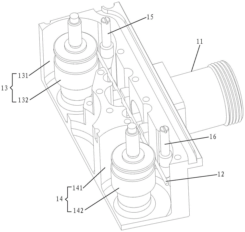
[0023] see figure 1 , figure 1 It is a port perspective view of an embodiment of the cavity coupling structure of the present invention. Such as figure 1 As shown, it includes: a cover plate (not shown in the figure), a cavity (not shown in the figure), a joint 11, a conductive member 12, a first resonator 13, a second resonator 14, a first adjustment member 15 and a second adjustment member 16. Wherein, the first resonator 13 includes a first resonant cavity 131 and a first resonant column 132 fixed in the first resonant cavity 131, and the second resonator 14 includes a second resonant cavity 141 and a resonant column fixed in the second resonant cavity 141. The second resonant column 142 .
[0024] In this embodiment, the first resonance column 132 and the second resonance column 142 are dielectric resonance columns, and the cavity coupling st...
PUM
 Abstract
Description
Claims
Application Information