System for surgical tool tracking

A surgical, tracker technology used in the field of systems that track the position and orientation of tools

Active Publication Date: 2014-09-10
MAKO SURGICAL CORP
View PDF5 Cites 4 Cited by
  • Summary
  • Abstract
  • Description
  • Claims
  • Application Information

AI Technical Summary

Problems solved by technology

One challenge with optical tracking is that a line of sight between the marker on the instrument being tracked and the sensing camera must generally b

Method used


Image

  • System for surgical tool tracking
  • System for surgical tool tracking
  • System for surgical tool tracking

Examples


Embodiment Construction

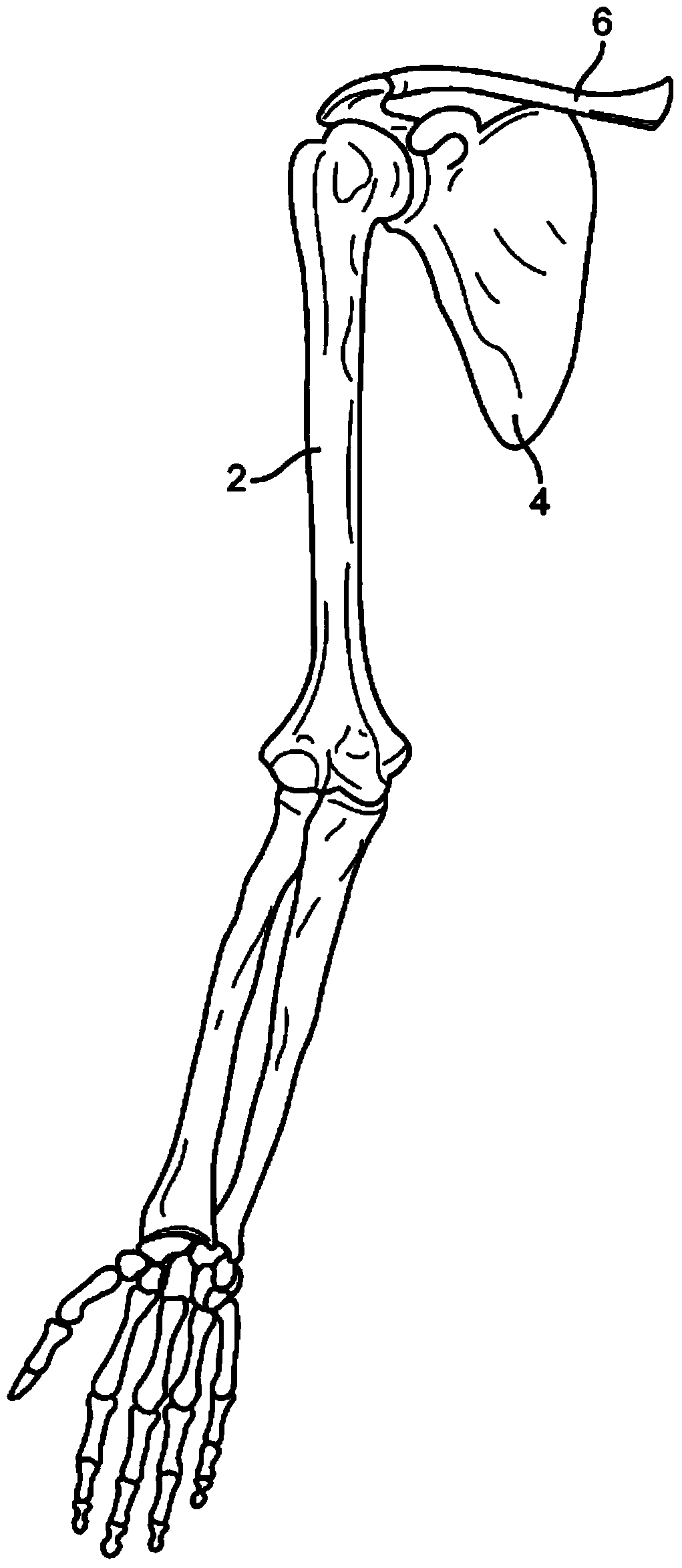
[0023] As described above, certain surgical techniques have evolved to rely on detailed knowledge of the spatial and rotational positioning of surgical instruments relative to target tissue. For example, in certain orthopedic surgical settings, it is desirable to utilize preoperative and intraoperative images and models of target tissue structures, as well as instruments (which are synchronized to coordinate a common system of instruments and anatomy), to predictably resolve Various target tissue structures. refer to figure 1, depicting some aspects of the skeletal anatomy of the shoulder, including the humerus (2), scapula (4), and clavicle (6). In scenarios where orthopedic surgical instruments are utilized to modify the geometry of one or more portions of this anatomy to repair damage, prepare prostheses, or other surgical goals, local mechanical trackers can be utilized intraoperatively to follow the intervention Rather, the position and orientation of the surgical instr...


PUM


Abstract

Systems and methods for robotic surgery are disclosed. In one embodiment, a system comprises a controller configured to control actuation of at least one servo motor; a surgical instrument configured to be movable in a workspace controlled, at least in part, by actuation of the at least one servo motor; and a mechanical tracker linkage coupled between the elongate instrument and a portion of skeletal anatomy of a patient, the tracker linkage comprising one or more joints associated with one or more joint rotation sensors and being configured to send joint signals to the controller; wherein the controller controls positioning of the instrument based at least in part upon the joint signals received from the mechanical tracker.

Description

[0001] Cross References to Related Applications [0002] This application claims priority to US Application Serial No. 13 / 276,048, filed October 18, 2011, the entire contents of which are incorporated herein by reference. technical field [0003] The present invention relates generally to surgical systems, and more particularly to systems and methods for tracking tool position and orientation during a surgical procedure. Background of the invention [0004] Minimally invasive surgery (MIS) is a surgical procedure performed through a much smaller incision than that used in traditional surgical approaches. For example, in orthopedic applications such as total knee replacement, MIS incision lengths can range from approximately 4 inches to 6 inches, while incision lengths in traditional total knee surgery typically range from 6 inches to 12 inches . MIS surgery is generally less invasive than traditional surgical approaches due to the smaller incision length, which minimizes s...

Claims


Application Information

Patent Timeline
IPC IPC(8): A61B19/00
CPCA61B19/2203A61B2019/467A61B2019/5259A61B17/16A61B2019/2238A61B2090/067A61B34/30A61B2034/306A61B2034/2059
Inventor H·康S·诺特曼
Owner MAKO SURGICAL CORP
Why Eureka
Try Eureka