
Method and vessel for laying a pipeline

A technology for laying ships and pipelines, which is used in pipe laying ships, pipeline laying and maintenance, machinery and equipment, etc.

Inactive Publication Date: 2014-09-10
SAIPEM SPA
View PDF11 Cites 5 Cited by
  • Summary
  • Abstract
  • Description
  • Claims
  • Application Information

AI Technical Summary

Problems solved by technology

This structure avoids the problems mentioned above for conventional S-laying, but can only be used in relatively deep water

Method used


Image

  • Method and vessel for laying a pipeline
  • Method and vessel for laying a pipeline
  • Method and vessel for laying a pipeline

Examples


Embodiment Construction

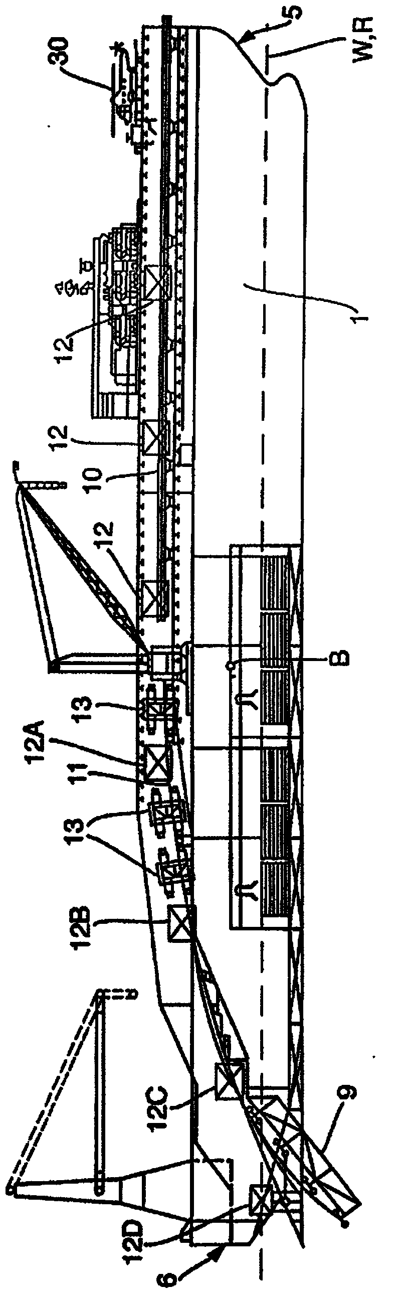
[0049] figure 1 For the same figure shown in WO2008 / 107186, reference may be made to that publication for further details of the boat. However, since the embodiments of the invention described below include modifications of the boat shown in the drawings of WO2008 / 107186, it is convenient to briefly describe the boat shown in this publication, the content of which is provided by Incorporated herein by reference.

[0050] The ship generally comprises a ship's hull 1 in which a plurality of prefabricated decks are defined for the prefabrication of joined pipe segments from a single length of pipe, on which a crane and other facilities. The bow 5 of the hull 1 is shown on the right and the stern 6 of the hull 1 is shown on the left, as in figure 1 observed in.

[0051] The hull 1 of the boat is of an unconventional design at its stern 6 having a starboard side and port ends between which an elongated recess is defined. This recess is open at the aft end of the hull 1 and als...


PUM


Abstract

A method of S-laying a pipeline from a vessel (103) is disclosed. A stinger (104) extends away from an end of the vessel (103) and the pipeline passes over the stinger (104) as it is laid from the vessel (103). The inclination of the pipeline to the horizontal increases as it passes along the stinger (104) and after it leaves the stinger (104) until it reaches an inflection point beyond the end of the stinger (104) at which the inclination of the pipeline to the horizontal is at a maximum. The inclination of the pipeline thereafter reduces until it touches down on the seabed. The method includes providing guides on the stinger (104) that limit lateral movement of the pipeline relative to the stinger (104) and moving the vessel (103) and the stinger (104) during S-laying to an orientation in which the longitudinal axis of the stinger (104) is inclined to the path of the pipeline (101) just laid on the seabed. The step of moving the vessel (103) and the stinger (104) comprises rotating the vessel (103) and the stinger (104) about a vertical axis passing through or adjacent to the inflection point.

Description

technical field [0001] The invention relates to a method of laying a pipeline and to a pipe-laying vessel. The method and vessel are particularly useful in the offshore industry related to oil and gas production. Background technique [0002] In the offshore industry, one of the tasks performed by certain vessels is to lay pipelines by S-lay or J-lay. [0003] In an "S" lay, the pipeline leaves the ship at an angle slightly or not inclined to the horizontal, adopts a steeper inclination in the water and then returns to a roughly horizontal arrangement on the seabed. The tension in the pipeline is usually adjusted by a series of track tensioners mounted on the ship along the pipe laying path. Track tensioners support the weight of the pipeline and control the passage of the pipeline. To achieve an S-lay, a stinger may be provided which is arranged to extend away from the end of the ship so that the pipeline passes over the stinger as it is laid from the ship and grows larg...

Claims


Application Information

Patent Timeline
Patent Type & Authority Applications(China)
IPC IPC(8): B63B35/03F16L1/18F16L1/20
CPCF16L1/205F16L1/18B63B35/03F16L1/225F16L1/20
Inventor 斯特凡诺·比安希罗伯托·布鲁斯基迭戈·拉扎林
Owner SAIPEM SPA
Learn More