Atomizing nozzle used for sanitary water outlet unit and sanitary faucet with water outlet unit

A technology of atomizing nozzles and water outlet parts, which is applied in the field of sanitary water faucets, and can solve problems such as manufacturing difficulties and complex structures

Active Publication Date: 2014-09-17
NEOPERL
View PDF13 Cites 5 Cited by
  • Summary
  • Abstract
  • Description
  • Claims
  • Application Information

AI Technical Summary

Problems solved by technology

However, this known device has a relatively complex structure which may cause difficulties in the manufacture of the device

Method used


Image

  • Atomizing nozzle used for sanitary water outlet unit and sanitary faucet with water outlet unit
  • Atomizing nozzle used for sanitary water outlet unit and sanitary faucet with water outlet unit
  • Atomizing nozzle used for sanitary water outlet unit and sanitary faucet with water outlet unit

Examples


Embodiment Construction

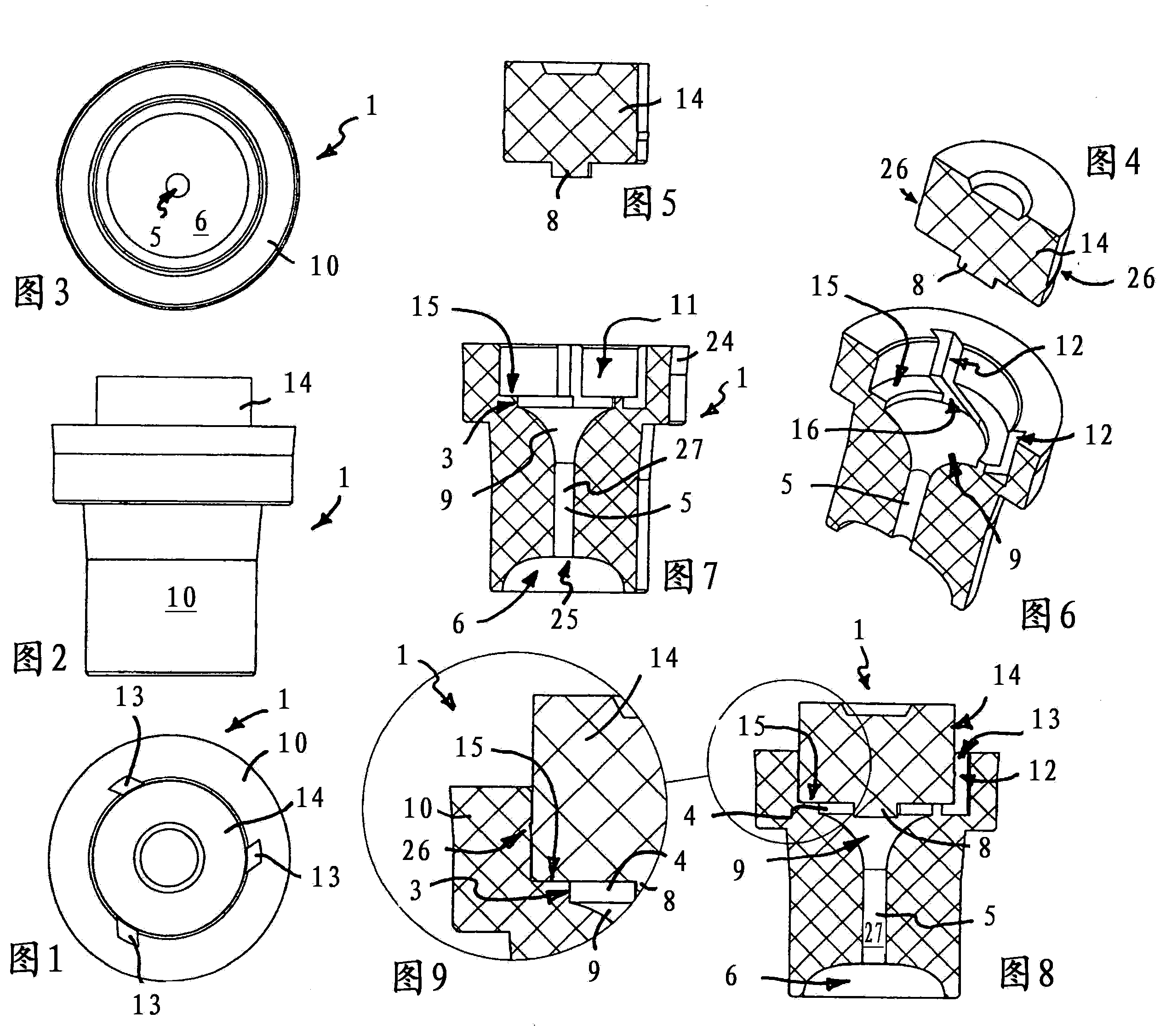
[0061] exist Figures 1 to 16 shows an atomizing nozzle 1 which is intended for a sanitary outlet for atomizing water under pressure. Whether the atomizing nozzle 1 is to be formed from a small volume stream or into an apparently volumetric, homogeneous water jet.

[0062] The atomizing nozzle 1 has a swirl chamber 2 which, on the inflow side, has a chamber section 3 with a substantially cylindrical or disk-shaped clear cross section. At least one supply channel 4 oriented transversely and preferably perpendicularly to the longitudinal axis of the nozzle and tangentially into the swirl chamber 2 opens into the swirl chamber 2 .

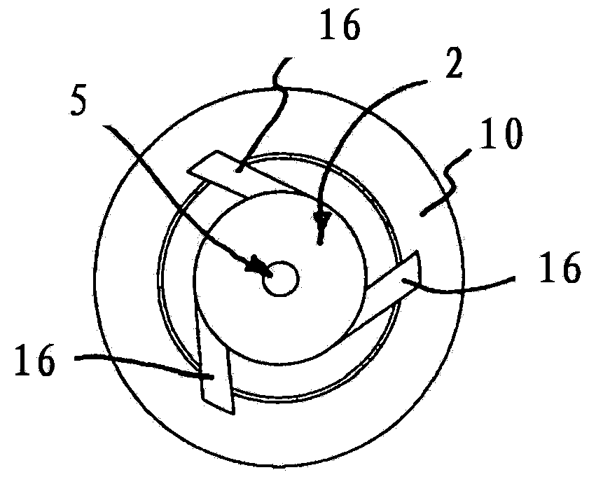
[0063] as in Figure 11 It can be seen in the top view in that the grooves 16 each forming a supply channel are shown in this figure, here a plurality of supply channels 4 which are evenly spaced apart from one another in the circumferential direction open into the vortex chamber 2 . The vortex chamber 2 tapers funnel-shaped in the outflow directio...


PUM


Abstract

The invention relates to an atomizing nozzle (1) used for a sanitary water outlet unit, and the atomizing nozzle (1) is used for atomizing water under pressure. The atomizing nozzle (1) provided by the invention is characterized in that the atomizing nozzle (1) is provided with a swirl chamber (2), at least one supplying channel (4) which is parallel to the longitudinal axis of the nozzle and enters the swirl chamber (2) in an approximately-tangent manner is introduced into the swirl chamber, and the swirl chamber (2) becomes thinner along the outflow direction and towards a nozzle channel (5). By employing the atomizing nozzle (1), a uniform water jet can be generated in a jet figure, although the water jet is small in volume, the the water jet makes people think that the water jet is big in volume.

Description

technical field [0001] The invention relates to an atomizing nozzle for atomizing water under pressure for a sanitary outlet. [0002] The invention also relates to a sanitary water tap with a water outlet. Background technique [0003] A device for spraying liquid under pressure is known from WO 2012 / 055051 A1, which device can be used as a spout of a sanitary tap or as a shower head. The known device has a central supply channel for the liquid which extends along the device axis. A plurality of swirl chambers are provided at intervals around the device axis and each have an inlet for feeding liquid into the respective swirl chamber and an outlet nozzle for discharging a liquid jet from the swirl chamber. The swirl chamber is connected to the supply channel via inlet channels which are arranged substantially transversely to the device axis. Each outlet nozzle is arranged obliquely to the longitudinal axis of the device in such a way that the individual liquid jets emergi...

Claims


Application Information

Patent Timeline
Patent Type & Authority Applications(China)
IPC IPC(8): B05B1/34B05B1/26B05B1/18F16K51/00
CPCB05B1/18B05B1/3415E03C1/086
Inventor H·许尔勒
Owner NEOPERL
Why Eureka
Try Eureka