
Welding surface design of spot welding

A welding surface and surface part technology, applied in welding equipment, welding equipment, resistance welding equipment, etc., can solve problems such as fragmentation, damage to welding performance, and complicated electrode dressing

Active Publication Date: 2014-09-17
GM GLOBAL TECH OPERATIONS LLC
View PDF5 Cites 23 Cited by
  • Summary
  • Abstract
  • Description
  • Claims
  • Application Information

AI Technical Summary

Problems solved by technology

[0006] While it is useful to form a weld pool at the desired location, high current densities can generate excessive heat at the contact block, which in turn can speed up the metallurgical reaction between the aluminum alloy comprising the workpiece and the copper alloy comprising the associated welding electrode
This reaction results in copper-aluminum build-up or contamination layers that accumulate on the welding electrode
If left undisturbed, contamination buildup can crumble and form pits in the welding electrode, which ultimately impairs welding performance and complicates electrode dressing

Method used


Image

  • Welding surface design of spot welding
  • Welding surface design of spot welding
  • Welding surface design of spot welding

Examples


Embodiment Construction

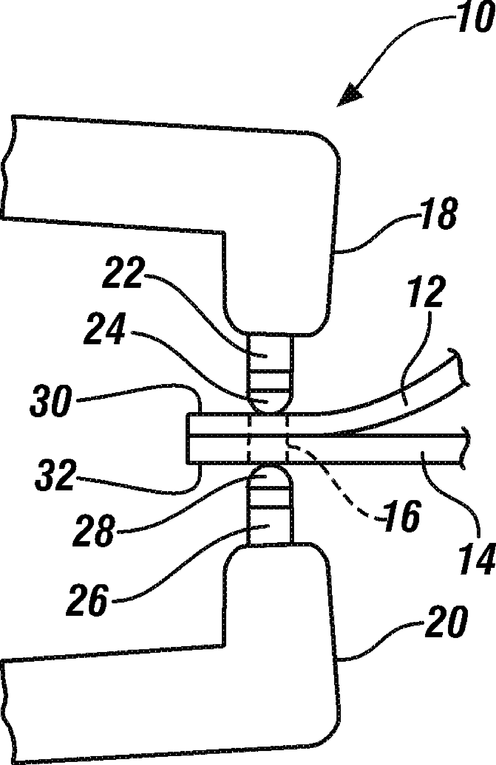
[0040] figure 1 A welding torch 10 is shown that may be used to resistance spot weld a first aluminum alloy workpiece 12 and a second aluminum alloy workpiece 14 at a welding location 16 . The first and second aluminum alloy workpieces 12, 14 are composed of an aluminum alloy such as an aluminum magnesium alloy, an aluminum silicon alloy, or an aluminum magnesium silicon alloy, and may be anywhere from about 0.5 mm to about 6.0 mm thick. A specific example of an aluminum alloy workpiece is 1.0 mm thick 5754-O aluminum alloy. But other aluminum alloys and specific workpiece thicknesses are possible. For this reason, the term "workpiece" as used herein refers broadly to include sheet metal layers, protrusions, castings, and other aluminum alloy pieces that are resistance spot weldable.

[0041] The welding gun 10 is typically part of a larger automated welding operation and includes a first gun arm 18 and a second gun arm 20 that are mechanically and electrically configured to r...


PUM


Abstract

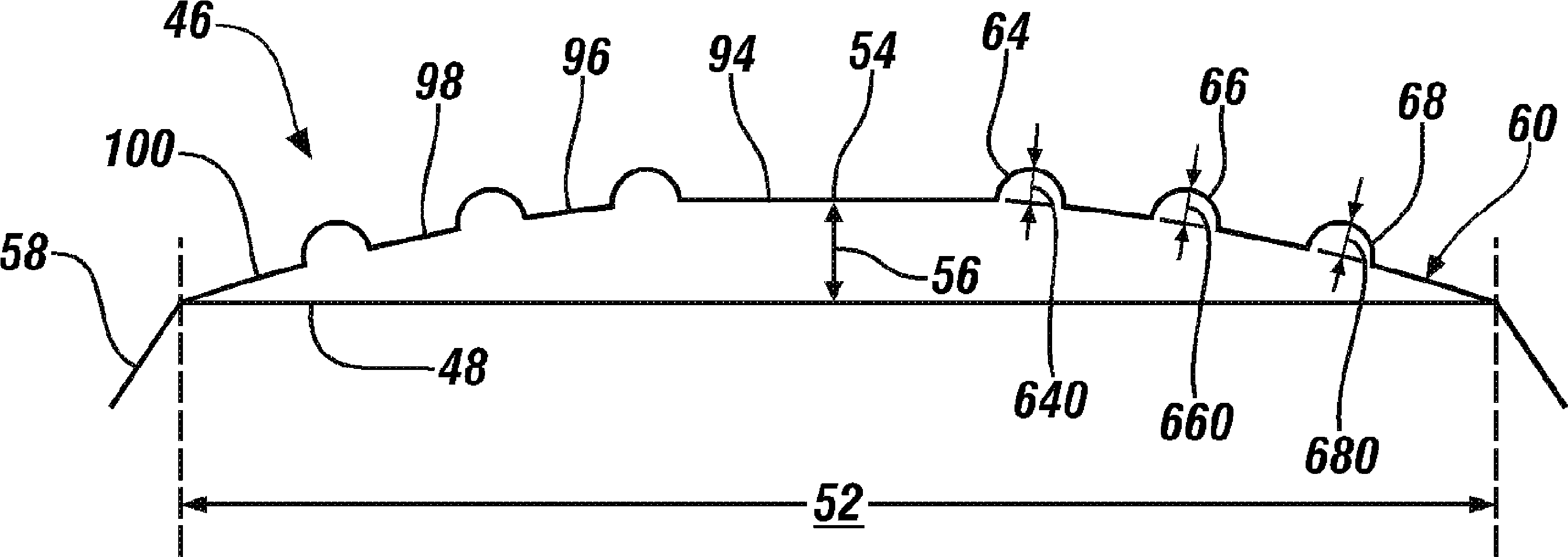
The invention relates to the welding surface design of spot welding. Specifically, a welding electrode for being engaged with an aluminum alloy workpiece during a spot welding process includes a welding surface, the welding surface comprises a base surface and a plurality of circular ridges projecting from the base surface to the outside, the circular ridges are dull and their presence on the welding surface provides some useful abilities for a first welding electrode, including the ability to make a better mechanical and electrical contact with the aluminum alloy workpiece.

Description

[0001] This application is a continuation-in-part of Serial No. 11 / 536,001, filed September 28, 2006, current US Patent Application Publication No. 2008 / 0078749. The entire content of this application is incorporated herein by reference. technical field [0002] The present disclosure generally relates to a welding electrode suitable for forming resistance spot welds, for example, in a stack of metal workpieces comprising at least one aluminum alloy workpiece. Background technique [0003] Some different types of body parts—such as doors, hoods, decklids, and liftgates, to name a few—comprise two or more metal pieces joined together. The metal workpieces may be at least partially joined by one or more resistance spot welds. These welds are usually formed around the perimeter of the body part or at some other bonding area. In the past, metal workpieces were often constructed of steel, and for this reason, and with regard to specific aspects of spot welding steel to steel, t...

Claims


Application Information

Patent Timeline
Patent Type & Authority Applications(China)
IPC IPC(8): B23K11/30B23K35/06
CPCB23K35/02B23K2201/18B23K11/185B23K11/31B23K11/3009B23K11/10B23K11/30B23K11/115B23K2203/10B23K35/002B23K35/0261B23K2101/18B23K2103/10
Inventor D.R.西勒M.J.卡拉古利斯
Owner GM GLOBAL TECH OPERATIONS LLC
Learn More