Improved structure for connecting wheel hub and steel wires

A technology of steel wire and hub, applied in the direction of wheels, spoked wheels, vehicle parts, etc., can solve the problems of easy column breakage, reduce efficiency, increase difficulty, etc., and achieve the effect of convenient installation

Inactive Publication Date: 2014-09-17
GIANT KUNSHAN
View PDF8 Cites 0 Cited by
  • Summary
  • Abstract
  • Description
  • Claims
  • Application Information

AI Technical Summary

Problems solved by technology

[0002] A bicycle wheel is composed of a rim, a hub, steel wires fixed on the rim and the hub, and tires on the rim respectively at both ends. At present, the fixing methods of the steel wire and the hub mainly include; one is that the end of the steel wire is bent into a Right angle, also known as J-shaped steel wire, the J-shaped steel wire passes through the corresponding fixing hole on the hub, and is positioned on the hub with the upper end of the steel wire, and the other end of the J-shaped steel wire is fixed on the rim, because the J-shaped steel wire has been severely bent , the J-shaped steel wire connected to one end of the hub is prone to breakage during use (even during installation), especially when riding on bumpy roads; the second is that the steel wire has ends, referred to as straight-pull steel wires. The steel wire has one end and one end is connected to the hub. First, the hub ring is processed into several grooves, and then the straight-pull steel wire has one end and one end is inserted into the corresponding groove, and the straight-pull steel wire is positioned by the end. The other end of the straight-pull steel wire is fixed to the rim. Since the straight-pull steel wire is not bent, the strength of the steel wire is increased. However, the design and processing of the groove on the hub are very demanding. The distribution of the groove must be It must be consistent with the specifications, and the extension direction of the groove must be consistent with the actual force direction at both ends of the straight-pull steel wire, so as to ensure a reliable connection between the steel wire and the hub. Therefore, the actual hub processing increases the difficulty and reduces the efficiency.

Method used


Image

  • Improved structure for connecting wheel hub and steel wires
  • Improved structure for connecting wheel hub and steel wires
  • Improved structure for connecting wheel hub and steel wires

Examples


Embodiment Construction

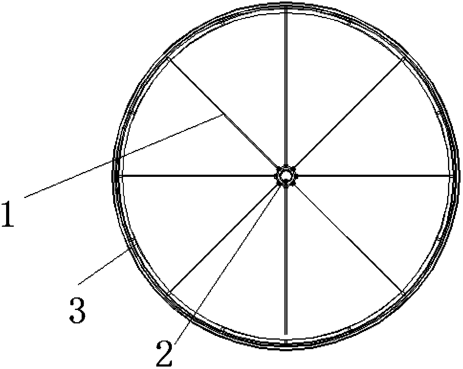
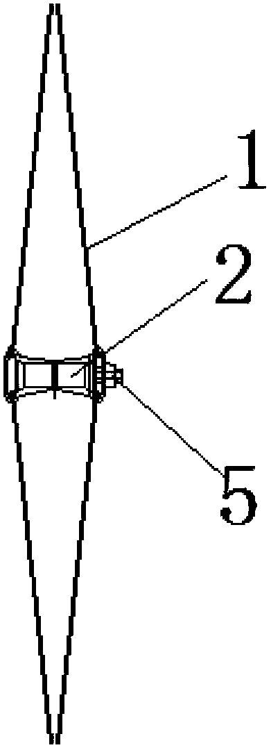
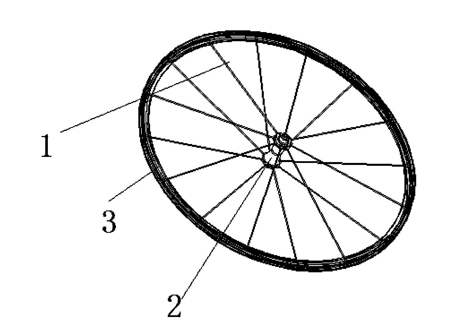
[0020] combine figure 1 , figure 2 , image 3 , Figure 4 with Figure 5 , as described in detail below:

[0021] An improved structure for connecting the hub of a wheel with steel wires, each steel wire on the wheel is a straight-pull steel wire 1 with an end 11, and the two sides of the hub 2 respectively form a plurality of connecting protrusions evenly distributed in the shape of a ring 21. Each of the connecting protrusions is provided with a fixing hole radially along the hub shaft hole. Each of the straight-pull steel wires 1 passes through a limiting block, and moves through the fixing hole on the corresponding connecting protrusion, and then is fixed to the wheel wheel. Ring 3, each of the limiting blocks forms an arc-shaped convex surface that facilitates the free rotation of the straight-pull steel wire.

[0022] In order to facilitate the free rotation of the straight-pull steel wire, each of the limiting blocks is a spherical washer 4, and the spherical wash...


PUM


Abstract

The invention provides an improved structure for connecting a wheel hub and steel wires. Each steel wire arranged on a wheel is a straight pulling steel wire provided with an end head, the circumferences of the two sides of the wheel hub are respectively provided with a plurality of connecting convex parts in annular belt-shaped uniform distribution, each connecting convex part is provided with a fixing hole along the radial direction of a shaft hole of the wheel hub, each straight pulling steel wire passes through a limiting block, movably passes through the fixing hole formed in the corresponding connecting convex part and is then fixedly arranged on a wheel rim of the wheel, each limiting block is provided with an arc-shaped convex surface convenient for the straight pulling steel wires to freely rotate, each limiting block is a spherical washer, each spherical washer is provided with a through hole convenient for the straight pulling steel wires to pass through, the inner circumferences of the two sides of the wheel hub are respectively provided with inner ring grooves, and the fixing holes formed in the connecting convex parts positioned at the same side of the wheel hub are distributed in the corresponding inner ring grooves. The improved structure has the advantages that the steel wires can be easily arranged on the wheel hub, in addition, the steel wires connected between the wheel hub and the wheel rim cannot be easily fractured, and a very useful value is realized.

Description

technical field [0001] The invention relates to the improvement of the wheel structure, in particular to the connection structure between the steel wire on the wheel and the hub, especially the connection and fixation between the steel wire of the bicycle wheel and the hub. Background technique [0002] A bicycle wheel is composed of a rim, a hub, steel wires fixed on the rim and the hub, and tires on the rim respectively at both ends. At present, the fixing methods of the steel wire and the hub mainly include; one is that the end of the steel wire is bent into a Right angle, also known as J-shaped steel wire, the J-shaped steel wire passes through the corresponding fixing hole on the hub, and is positioned on the hub with the upper end of the steel wire, and the other end of the J-shaped steel wire is fixed on the rim, because the J-shaped steel wire has been severely bent , the J-shaped steel wire connected to one end of the hub is prone to breakage during use (even during...

Claims


Application Information

Patent Timeline
Patent Type & Authority Applications(China)
IPC IPC(8): B60B1/04
Inventor 周铭恩
Owner GIANT KUNSHAN
Why Eureka
Try Eureka