
Wireless video transmission emergency lamp with smoke detector

A technology of wireless video and emergency lights, applied in the field of fire-fighting equipment, can solve the problem of single function of emergency lights and achieve the effect of improving the efficiency of fire-fighting work

Inactive Publication Date: 2014-09-17
SHAANXI EYOUNG TECH
View PDF0 Cites 0 Cited by
  • Summary
  • Abstract
  • Description
  • Claims
  • Application Information

AI Technical Summary

Problems solved by technology

[0003] The purpose of the present invention is to overcome the problem of the single function of the existing emergency light, and specifically provide a new type of emergency light that can directly transmit the video picture of the fire scene to the fire control headquarters. The emergency light also has the function of smoke monitoring

Method used


Image

  • Wireless video transmission emergency lamp with smoke detector

Examples


Embodiment 1

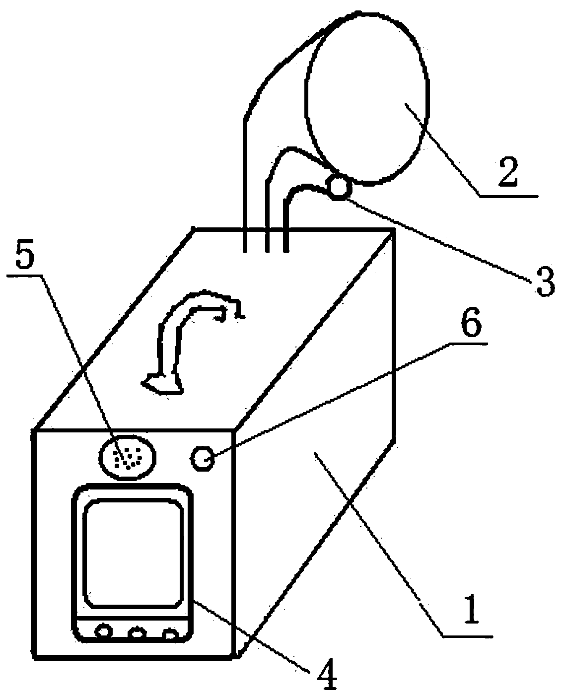
[0012] A wireless video transmission emergency light with a smoke detector, including a base 1, a lamp body 2, and an emergency light battery installed in the base 1, the emergency light battery is connected to the light body 2, and a pass switch 6 is provided on the base surface A smoke detector 5 connected to the battery of the emergency light; a display 4 is also arranged on the base surface, a microprocessor, a 3G wireless communication module and a power module are arranged inside the base 1, and a camera 3 is also arranged on the edge of the lamp body 2 , the power supply module is electrically connected with the camera 3, the display 4, the microprocessor, the 3G wireless communication module and the battery of the emergency light respectively, and the microprocessor is connected with the 3G wireless communication module, the camera 3 and the display 4 respectively.

[0013] The wireless video transmission system of the present invention supports the transmission of vide...

Embodiment 2

[0016] On the basis of Embodiment 1, the display 4 , the smoke detector 5 and the switch 6 are all arranged on the rear surface of the base 1 , and the display 4 is provided with a switch and a video transmission button. The 3G wireless communication module is provided with a SIM card slot. The display is arranged on the rear surface of the base, which is beneficial to on-site firefighters to watch the real-time recording video effect, and facilitates their on-site recording operation. After the switch button on the display is pressed, the video recording function will be turned on, and when the video transmission button is pressed and the headquarters equipment is connected, the real-time recorded video will be transmitted to the headquarters.


PUM


Abstract

The invention belongs to the technical field of fire equipment, and specifically provides a wireless video transmission emergency lamp with a smoke detector. The wireless video transmission emergency lamp comprises a base, a lamp body, and emergency lamp storage batteries arranged in the base, wherein the emergency lamp storage batteries are connected with the lamp body, and a smoke detector connected to the emergency lamp storage batteries through a switch is arranged on the surface of the base; a display is also arranged on the surface of the base, and a microprocessor, a 3G (third generation) wireless communication module and a power module are arranged inside the power module; a camera is also arranged on the edge of the lamp body, and the power module is respectively and electronically connected with the camera, the display, the microprocessor, the 3G wireless communication module and the emergency lamp storage batteries; the microprocessor is respectively connected with the 3G wireless communication module, the camera and the display. The wireless video transmission emergency lamp provided by the invention has the advantages of directly transmitting a fire scene video to a fire command department to facilitate the command department to quickly see a fire scene, thereby improving the fire control work efficiency; in addition, the wireless video transmission emergency lamp also has a smoke monitoring function in the presence of the smoke detector on the emergency lamp.

Description

technical field [0001] The invention belongs to the technical field of fire fighting equipment, and in particular relates to a wireless video transmission emergency light with a smoke detector. Background technique [0002] When a fire or emergency event occurs, there will often be a power outage. If it is during the day, the impact will not be great, but if it is at night, it will cause great inconvenience. Therefore, emergency lights have appeared on the market. It is an indispensable fire rescue appliance for residents or fire rescue personnel. However, the existing emergency lights have a single function, and ordinary emergency lights only have the basic functions of charge and discharge management and emergency lighting, and it is difficult to provide more help to the rescued and firefighters at the fire rescue scene. Contents of the invention [0003] The purpose of the present invention is to overcome the problem of the single function of the existing emergency lig...

Claims


Application Information

Patent Timeline
Patent Type & Authority Applications(China)
IPC IPC(8): F21S9/02F21V23/04F21V33/00H04N7/18
Inventor 张俊
Owner SHAANXI EYOUNG TECH
Learn More