
Display Module

A technology for displays and display panels, applied in the directions of instruments, light guides, optics, etc., can solve the problems of tape loosening, jumping off, and displacement of optical films of optical films, and achieve the effect of proper fixation

Active Publication Date: 2014-09-17
AU OPTRONICS CORP
View PDF9 Cites 6 Cited by
  • Summary
  • Abstract
  • Description
  • Claims
  • Application Information

AI Technical Summary

Problems solved by technology

Under such a structure, the most common situation is that when the impact or drop test is passed, it is likely to cause the tape fixing the uppermost optical film to loosen, making the second and third optical films below The positioning lugs of the film (middle optical diaphragm) jump out of the positioning groove of the plastic frame, causing the displacement of these middle optical diaphragms

Method used


Image

  • Display Module
  • Display Module
  • Display Module

Examples


Embodiment Construction

[0054] Certain terms are used throughout the specification and following claims to refer to particular elements. Those of ordinary skill in the art will appreciate that manufacturers may refer to the same element by different terms. The scope of this specification and the following claims does not use the difference in name as the way to distinguish components, but the difference in function of the components as the criterion for distinguishing. The "comprising" mentioned throughout the specification and subsequent claims is an open term, so it should be interpreted as "including but not limited to". Furthermore, the terms "coupled" or "connected" herein include any direct or indirect electrical or structural means of connection. Therefore, if it is described in the text that a first device is coupled / connected to a second device, it means that the first device may be directly electrically / structurally connected to the second device, or indirectly electrically / structurally co...


PUM


Abstract

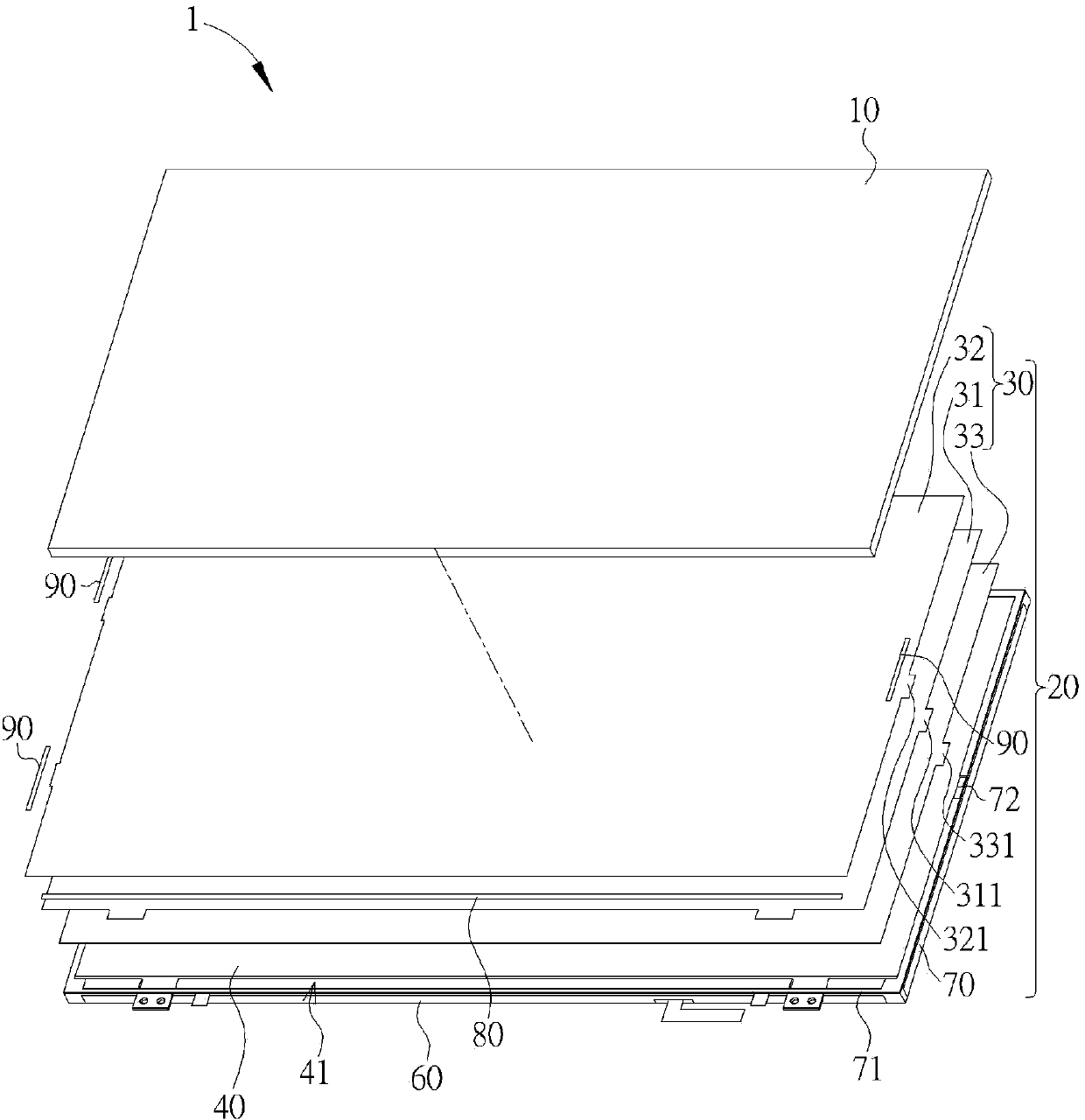
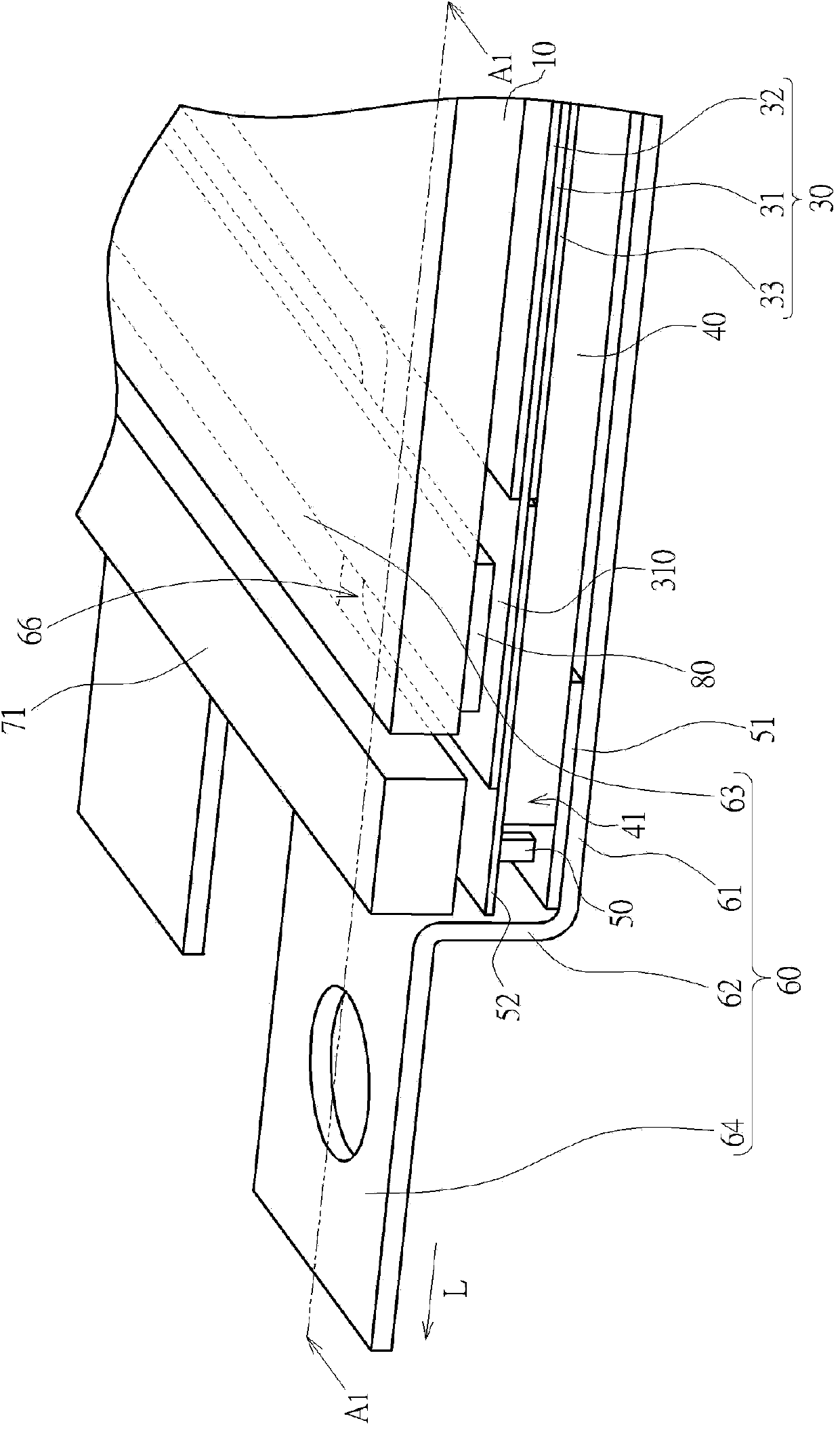
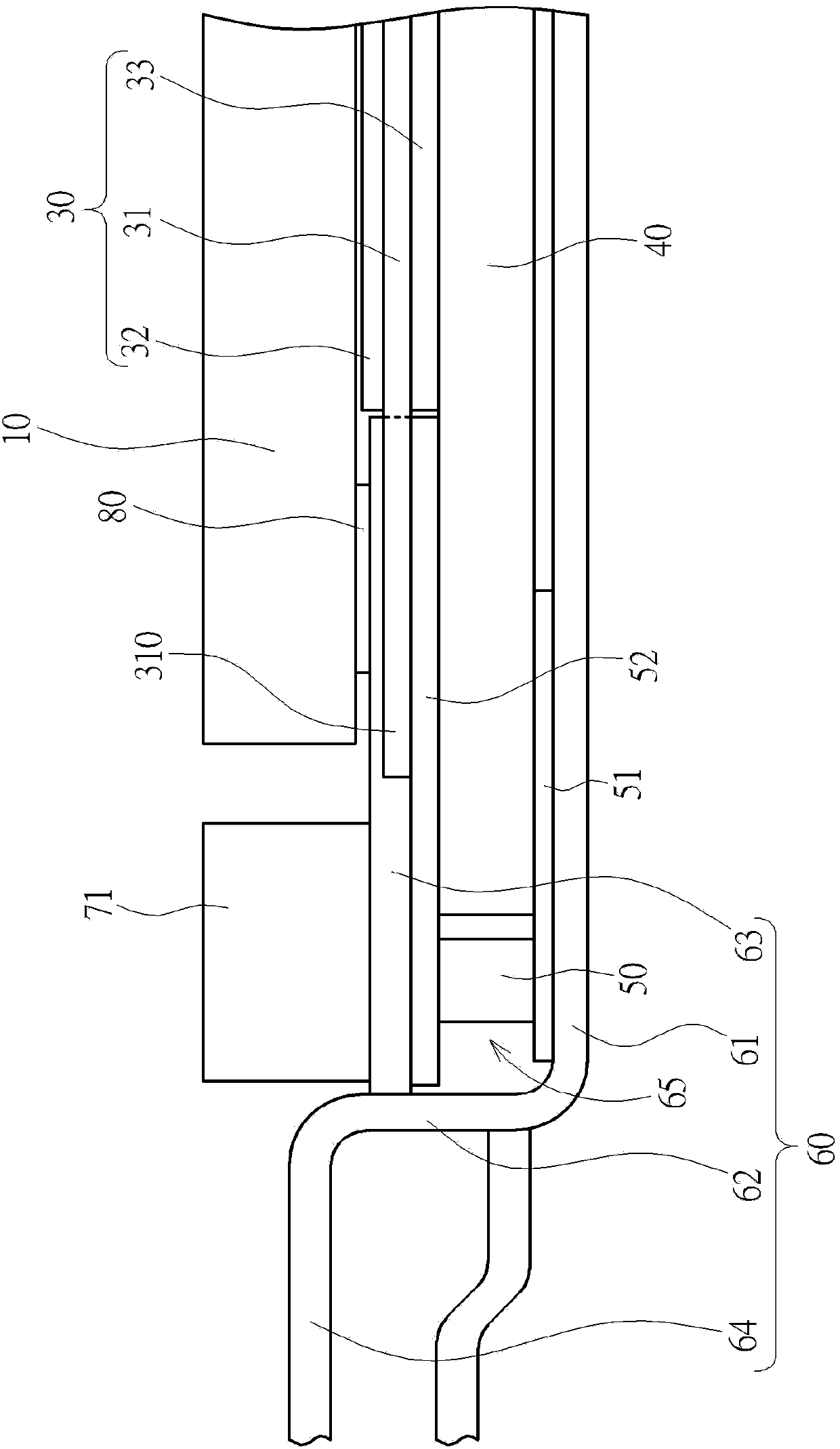
The invention discloses a display module. In a backlight module of a display module body, multiple overlapped optical film sheets on a non-light source side are arranged in a positioning groove of a frame body of a rubber frame by positioning lugs, so the optical film sheets can be correctly positioned when arranged on a light guiding element. Middle optical film sheets of the optical film sheets form outwards-protruding fixed lugs corresponding to a light source side. After existing system supports are bent, holes are formed in a framework on the light source side, so the fixed lugs of the middle film sheets are allowed to extend into the holes. Double-faced adhesion elements arranged between a display panel and the framework are used for fixing the fixed lugs of the middle film sheets, so the middle film sheets of the optical film sheets of the backlight module can be well fixed and are protected from collision or falling in a dropping test.

Description

technical field [0001] The invention relates to a display module, in particular to a display module with a structure for fixing an intermediate film on the light source side of a backlight module. Background technique [0002] The flat panel display module usually includes a backlight module and a panel module, wherein the backlight module is arranged at the bottom of the panel module to provide the light source required by the display module. Generally, the backlight module includes a plurality of optical films disposed on the light guide element to uniformize, brighten, polarize, etc. the light emitted from the light guide element. Usually the optical film is positioned by the plastic frame (used to carry the panel module) around the light guide element. Generally, a positioning groove is formed on the side of the plastic frame that is not the light source side, and these optical films are then positioned. The lugs for positioning are grown at the corresponding positions....

Claims


Application Information

Patent Timeline
Patent Type & Authority Applications(China)
IPC IPC(8): G02F1/1333G09F9/00
CPCG02B6/0091G02B6/0088
Inventor 黄俊棨张正伟杨秉昌庄淑婷
Owner AU OPTRONICS CORP
Learn More