I-shaped steel welding device

A welding device and I-beam technology, applied in auxiliary devices, welding equipment, auxiliary welding equipment, etc., can solve the problems that H-beams are prone to shaking or shifting, affecting the success rate of H-beam welding, and hidden safety hazards of H-beam scrapping , to achieve the effect of saving manpower, improving welding efficiency and high degree of automation

Inactive Publication Date: 2020-03-06
XUZHOU MASTER MECHANICAL TECH CO LTD
View PDF7 Cites 1 Cited by
  • Summary
  • Abstract
  • Description
  • Claims
  • Application Information

AI Technical Summary

Problems solved by technology

[0004] Although this invention can weld two H-shaped steels at the same time, it is difficult to weld both sides of an H-shaped steel at one time in this patent, requiring workers to manually change the positions of the H-shaped steels, which brings great trouble to the workers ; Although this patent can lack the fixing device for the H-shaped steel, it is easy to shake or shift the H-shaped steel in the welding process, which affects the success rate of the H-shaped steel welding, and makes the H-shaped steel have a safety hazard of being scrapped; this patent can only One side of the H-shaped steel is welded, and both sides of the H-shaped steel need to be welded, so that the worker needs to manually turn over the H-shaped steel, which will bring greater labor intensity to the worker.

Method used


Image

  • I-shaped steel welding device
  • I-shaped steel welding device

Examples


specific Embodiment 1

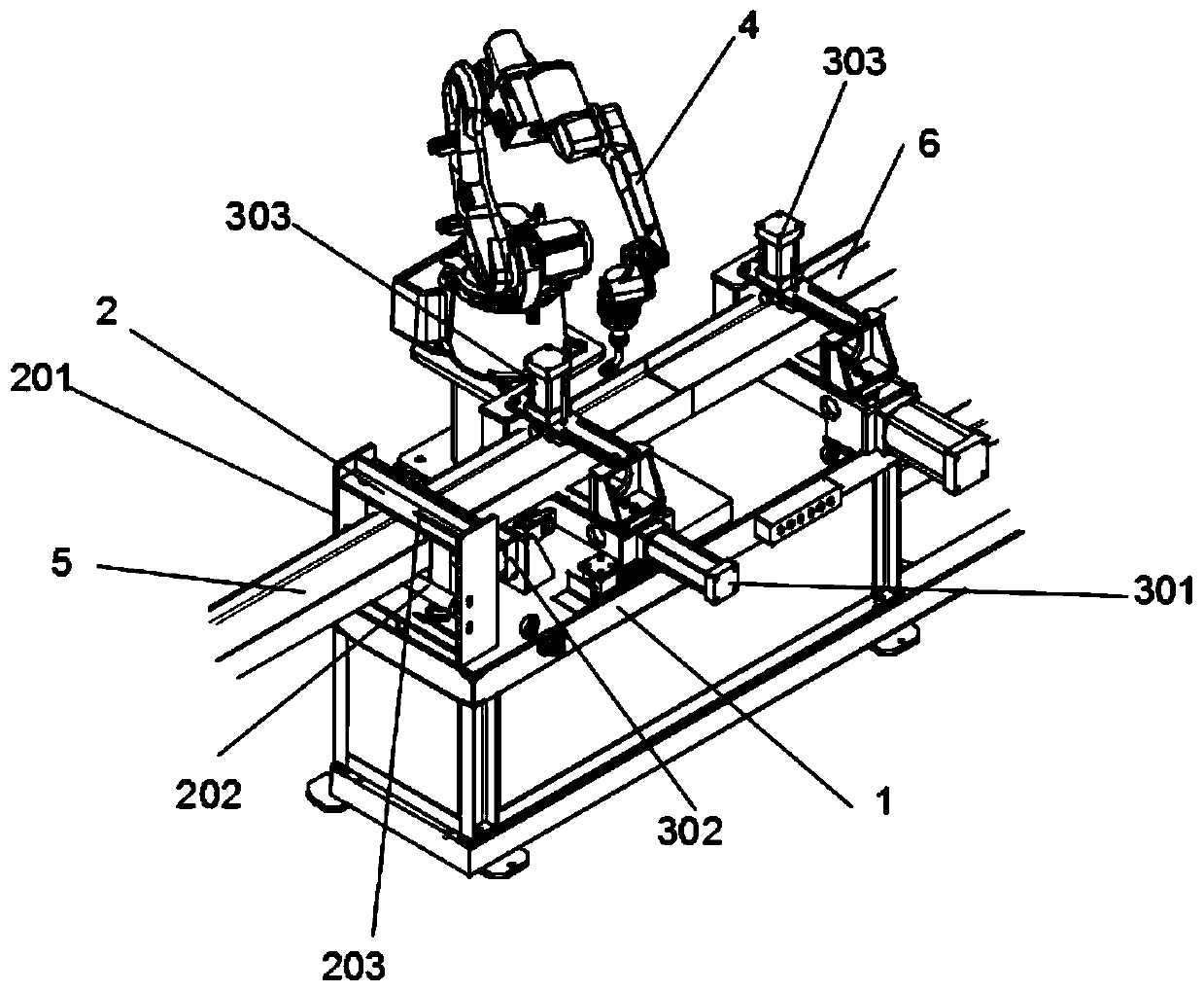
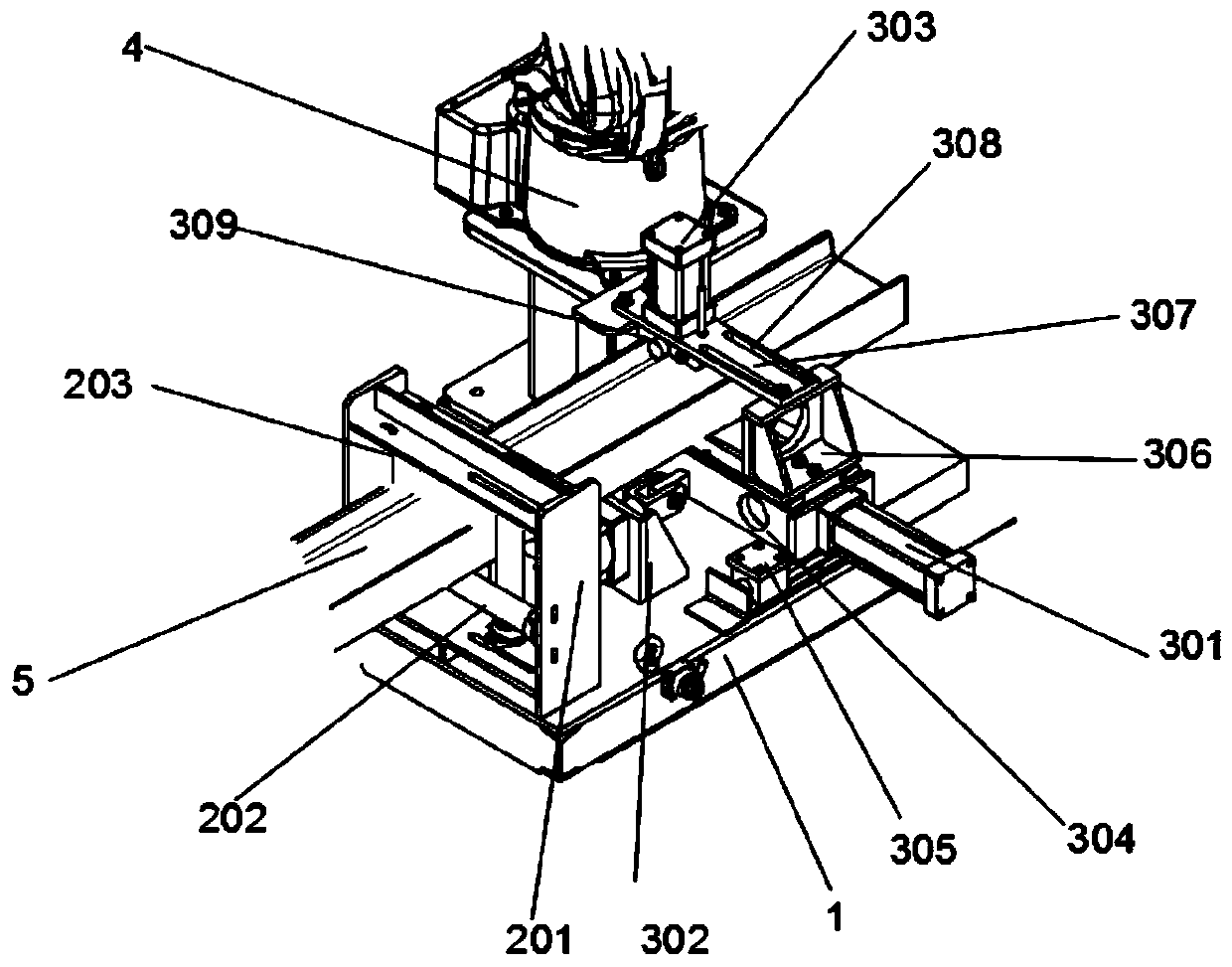
[0027] Specific embodiment 1. An I-beam welding device includes a welding device body. The welding device body includes a rectangular frame 1. The bottom of the frame 1 is fixed with a base and the top is an operating platform. The top of the frame 1 is fixedly connected with a limit mechanism 2 , a positioning mechanism 3 and a welding mechanism 4 .

[0028] Wherein the position limiting machine 2 includes a first fixed frame 201 arranged vertically, and two fixed frames 201 are arranged symmetrically on both sides of the frame 1 . The bottom of the first fixed frame 201 is fixed with a roller 202 , and the top of the first fixed frame 201 is fixed with a limit rod 203 ; the limit rod 203 is arranged parallel to the top of the frame 1 . The rollers 202 are located away from the bottom of the frame 1 .

[0029] The positioning mechanism 3 includes a first cylinder 301 , a second cylinder 302 and a third cylinder 303 . The first cylinder 301 is arranged along the width direct...


PUM


Abstract

The invention discloses an I-shaped steel welding device. The device comprises a welding device body, wherein the welding device body comprises a rack; a limiting mechanism, positioning mechanisms anda welding mechanism are fixedly connected to the top of the rack; the limiting mechanism comprises vertically arranged first fixing frames; a roller is fixedly connected to the bottom of each first fixing frame; a limiting rod is fixedly connected to the top of each first fixing frame; each positioning mechanism comprises a first air cylinder, a second air cylinder and a third air cylinder; eachfirst air cylinder is arranged along the width direction of the rack; a second fixing frame is fixedly connected to the end part of each first air cylinder; a sliding table is slidably connected to the bottom of each second fixing frame; one side of each second fixing frame is fixedly connected with an output shaft of the corresponding second air cylinder through a fastener; supporting frames arefixedly connected to the two sides of the top of each second fixing frame; a cross beam is fixedly connected to the tops of the supporting frames on the top of each second fixing frame; each third aircylinder is fixedly connected to the corresponding cross beam; and end, close to the corresponding first air cylinder, of each cross beam is provided with sliding grooves. The I-shaped steel weldingdevice is simple in structure, high in automation degree, accurate in alignment, and capable of improving the working efficiency and saving the manpower.

Description

technical field [0001] The invention relates to the technical field of steel structure processing equipment, in particular to an I-beam welding device. Background technique [0002] The I-beam is a long strip of steel with a groove-shaped cross-section. It belongs to carbon structural steel for construction and machinery. It is a section steel with a complex cross-section. I-beams are mainly used in building structures, curtain wall engineering, mechanical equipment and vehicle manufacturing. In practical applications, it is often necessary to weld I-beams of different lengths together, but currently there is no mechanical equipment for efficiently welding I-beams. [0003] The I-beam is similar to the "H"-shaped steel structure, and has many common features, and the welding process also has many similarities. The patent No. CN107378330A is an invention patent for an H-shaped steel welding device, including a bracket group, guide rails, door beams and a cantilever welder. ...

Claims


Application Information

Patent Timeline
Patent Type & Authority Applications(China)
IPC IPC(8): B23K37/02B23K37/04B23K103/04
CPCB23K37/0252B23K37/0443B23K2103/04
Inventor 郭楠楠
Owner XUZHOU MASTER MECHANICAL TECH CO LTD
Why Eureka
Try Eureka