

Control device of elevator
An elevator control device and elevator technology, which are applied in the field of elevator control devices, can solve the problems of not considering the load of the car and the inability of the car to stop, etc.
- Summary
- Abstract
- Description
- Claims
- Application Information
AI Technical Summary
Problems solved by technology
Method used
Image

Examples
no. 1 Embodiment approach
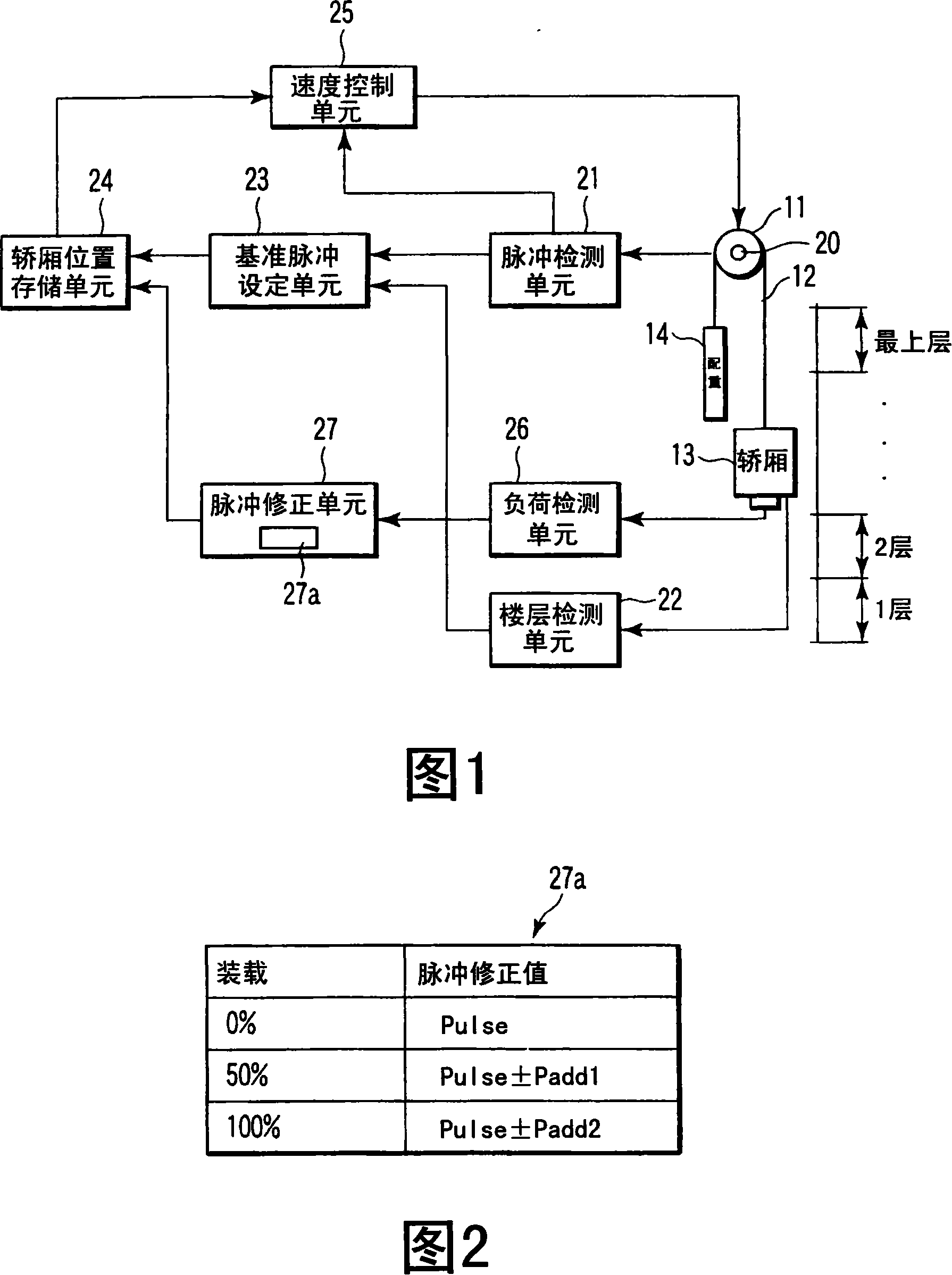
[0028] Fig. 1 is a block diagram showing the configuration of an elevator control device according to a first embodiment of the present invention. 11 among the figure is hoisting machine, rotates by the driving of electric motor. The car 13 and the counterweight 14 move up and down in the hoistway by the cable 12 wound around the hoist 11 .
[0029] Among them, the elevator control device of this embodiment has a pulse detection unit 21 , a floor detection unit 22 , a reference pulse setting unit 23 , a car position storage unit 24 , a speed control unit 25 , a load detection unit 26 and a pulse correction unit 27 .
[0030] A rotation detector 20 constituted by a pulse encoder or the like is attached to the rotation shaft of the hoist 11 . The pulse detection unit 21 detects a pulse signal output from the rotation detector 20 accompanying the rotation of the hoist 11 . The floor detection unit 22 detects the floor position of the car 13 (that is, the position where the car ...
no. 2 Embodiment approach
[0049] Next, a second embodiment of the present invention will be described.
[0050] In the second embodiment, the reference pulse is corrected in consideration of the loading load and the running direction of the car.
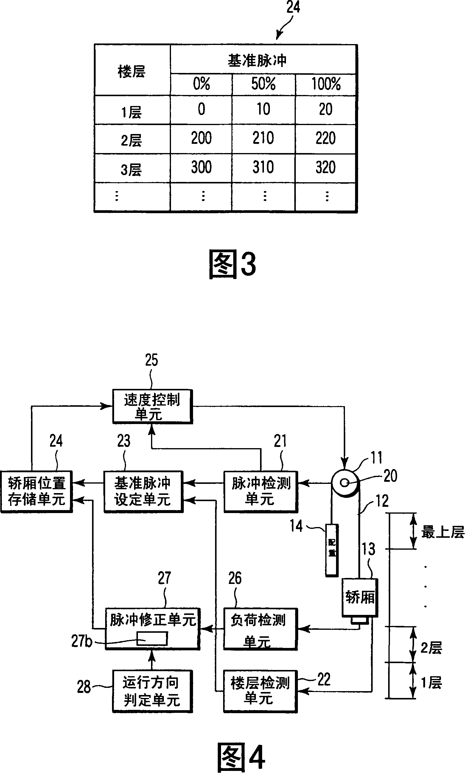
[0051] Fig. 4 is a block diagram showing the configuration of an elevator control device according to a second embodiment of the present invention. In addition, the basic structure is the same as that of FIG. 1 of the above-mentioned first embodiment, and the same parts are denoted by the same reference numerals, and description thereof will be omitted.
[0052] The difference from the structure of FIG. 1 is that not only the running direction determination means 28 is added to this device, but also the second correction table 27b is provided in the pulse correction means 27 . The running direction judging unit 28 judges the running direction of the car 13 according to the running command input from the outside. Pulse correction values for different motio...
no. 3 Embodiment approach
[0063] Next, a third embodiment of the present invention will be described.
[0064] In the third embodiment, a rotation detector is provided on a rotating body directly related to the movement of the car. The above-mentioned rotating body is specifically a speed governor.
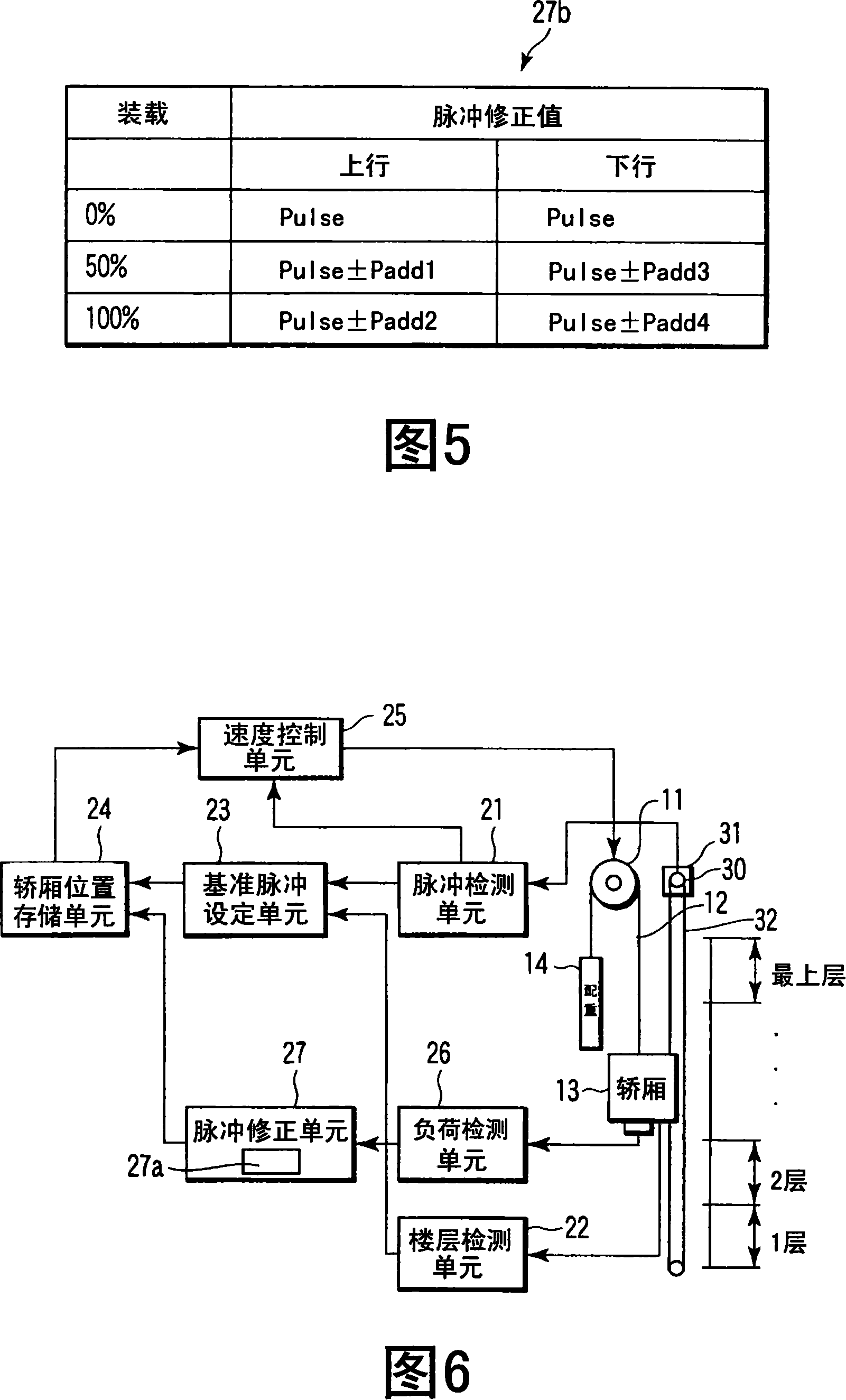
[0065] Fig. 6 is a block diagram showing the configuration of an elevator control device according to a third embodiment of the present invention. In addition, the basic structure is the same as that of FIG. 1 in the above-mentioned first embodiment, and the same reference numerals are assigned to the same parts, and description thereof will be omitted.
[0066] The difference from the configuration of FIG. 1 is that a rotation detector 30 is provided in the speed governor 31 . The governor 31 is a device for regulating the running speed of the car 13 . This governor 31 is called a governor. The car 13 is attached to the governor 31 via a governor rope 32 and rotates as the car 13 runs. A rotation det...
PUM
 Abstract
Description
Claims
Application Information