Full-pneumatic hanging table sweeping head machining clamping set

An all-pneumatic and clamping technology, applied in the field of workpiece processing, can solve the problems of time-consuming, labor-intensive, inability to clamp flat, affecting accuracy, etc., and achieve the effect of simple and fast operation, convenient and precise fixing, and high machining accuracy.

Inactive Publication Date: 2016-05-04
KUNSHAN MINAMAX PRECISION IND
View PDF7 Cites 1 Cited by
  • Summary
  • Abstract
  • Description
  • Claims
  • Application Information

AI Technical Summary

Problems solved by technology

[0003] One is to use a special row clamp to fix the thimble vertically and finish it with the front of the grinding wheel. The disadvantage of this processing method is that it is suitable for a small range of specifications, and the thimble cannot be processed for thick and long types (total length > 300mm, rod diameter > Φ16mm).
[0004] The other is to use a common vise to fix the thimble horizontally and finish it with the side of the grinding wheel. The disadvantage of this processing method is that due to the structure of the common vise (the V-groove is on the side of the slider), the thick / long thimble is due to Due to the gravity factor, it cannot be clamped flat, and the repeatability is poor, resulting in the unfavorable situation that the end surface of the thimble and the shaft are tilted (the error of high and low points is 0.05~0.1), which seriously affects the quality; the clamping needs to be inserted from the front end of the vise into the jaw of the vise for clamping Therefore, it will inevitably cause shovel (scraping) friction between the sharp edge of the thimble and the clamping surface of the vise, causing damage to the vise (scraping irregular grooves on the clamping surface), seriously affecting the accuracy; manual operation is time-consuming and laborious

Method used


Image

  • Full-pneumatic hanging table sweeping head machining clamping set
  • Full-pneumatic hanging table sweeping head machining clamping set
  • Full-pneumatic hanging table sweeping head machining clamping set

Examples


Embodiment Construction

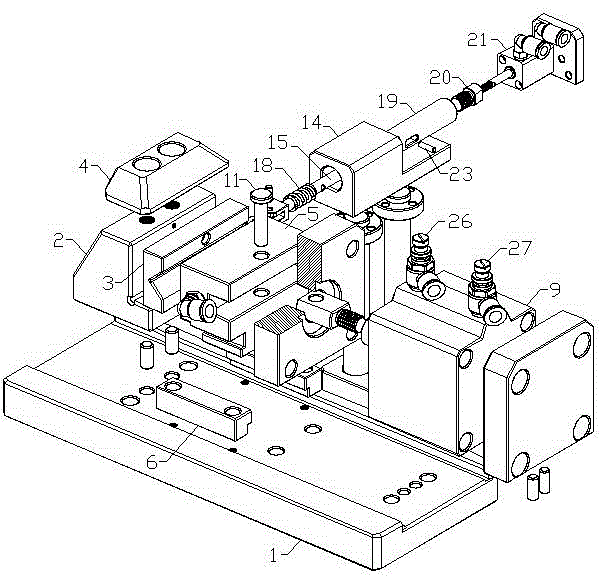
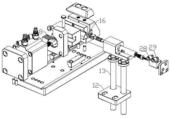
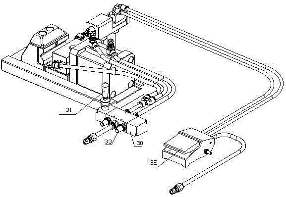
[0024] The present invention will be further described below in conjunction with the accompanying drawings.

[0025] Such as Figure 1-Figure 4 As shown in the figure, a clamping group for all-pneumatic hanging table sweeping head processing includes a base plate 1, one end of the base plate 1 is provided with a fixed block 3, and the other end is provided with a clamping slider that can move horizontally relative to the fixed block 3 5, and the side surface of the fixed block 3 opposite to the clamping slider 5 is provided with a V-shaped groove; the clamping slider 5 is driven by the first cylinder 9, and the first cylinder 9 is driven by two The air pipe and the manual reversing valve 30 are connected with the air source, and the manual reversing valve 30 is provided with a reversing valve handle 31 . One side of the fixed block 3 is provided with a jack pulley 16 which has the same height as the V-shaped groove, and the jack pulley 16 is connected with the second cylinder...


PUM


Abstract

The invention discloses a full-pneumatic hanging table sweeping head machining clamping set which comprises a base plate. One end of the base plate is provided with a fixed block, and the other end of the base plate is provided with a clamping sliding block capable of horizontally moving relative to the fixed block. A V-shaped groove is formed in the surface of the side, opposite to the clamping sliding block, of the fixed block. The clamping sliding block is driven by a first air cylinder. The first air cylinder is connected with an air source through two air pipes and a hand-directional valve. The hand-directional valve is provided with a directional valve handle. One side of the fixed block is provided with an ejector rod pulley with the same height as the V-shaped groove. The ejector rod pulley is connected with a second air cylinder through an ejector rod. One end of the V-shaped groove is the fixed end, the first air cylinder is used as a clamping force supply source, the second air cylinder is utilized for pushing the ejector rod pulley to achieve fit between product benchmark and clamping set positioning benchmark, the hand-directional valve is utilized for carrying out clamping set opening and clamping motion switch control, a pedal directional valve is utilized for controlling the ejector rod pulley to be pushed out and taken back, operation is easy and fast, and machining precision is high.

Description

technical field [0001] The invention relates to a processing and clamping group for a full pneumatic hanging table sweeping head, which belongs to the technical field of workpiece processing. Background technique [0002] For the processing of the head of the ejector pin, it is necessary to fix the pole and use the grinding wheel to finish it. The existing processing methods are as follows. [0003] One is to use a special row clamp to fix the thimble vertically and finish it with the front of the grinding wheel. The disadvantage of this processing method is that it is suitable for a small range of specifications, and the thimble cannot be processed for thick and long types (total length > 300mm, rod diameter > Φ16mm). . [0004] The other is to use a common vise to fix the thimble horizontally and finish it with the side of the grinding wheel. The disadvantage of this processing method is that due to the structure of the common vise (the V-groove is on the side of t...

Claims


Application Information

Patent Timeline
Patent Type & Authority Applications(China)
IPC IPC(8): B24B41/06B24B55/06
CPCB24B41/065B24B55/06
Inventor 李芳
Owner KUNSHAN MINAMAX PRECISION IND
Why Eureka
Try Eureka