
ptc heater

A heater and temperature controller technology, applied in the direction of electric heating devices, ohmic resistance heating, ohmic resistance heating parts, etc., can solve the problems of unfavorable manufacturing and assembly, unfavorable technical inspiration, unfavorable resource saving and economical efficiency, etc. To achieve the effect of convenient manufacturing and assembly, concise overall structure and resource saving

Active Publication Date: 2015-10-07
嘉善县魏塘资产管理有限公司
View PDF11 Cites 5 Cited by
  • Summary
  • Abstract
  • Description
  • Claims
  • Application Information

AI Technical Summary

Problems solved by technology

[0005] However, disposing two or more PTC heaters to the air conditioner in a simple way of duplication will produce the following technical problems: because if the number of tailstocks and electrical connectors is combined with the number of PTC heater bodies To maintain a step-by-step relationship, specifically, when there are two PTC heater bodies, if two tailstocks and two electrical connection seats are used, the following technical problems will undoubtedly occur: First, due to the multiplied number of parts , so it is not conducive to manufacturing and assembly; second, due to the increase in the number of components, it will be limited by the limited space in the indoor unit, and even interfere with other components; third, it is not conducive to saving resources and reflecting economy
Undoubtedly, using one tailstock and one electrical connection seat for two or more PTC heater bodies can solve this technical problem, that is to say, regardless of the number of PTC heater bodies, the tailstock and electrical connection seat are always one , but there is no corresponding technical revelation in the patent and non-patent literature published so far

Method used


Image

  • ptc heater
  • ptc heater
  • ptc heater

Examples


Embodiment Construction

[0023] In order to enable the examiners of the patent office, especially the public, to understand the technical essence and beneficial effects of the present invention more clearly, the applicant will describe in detail the following in the form of examples, but none of the descriptions of the examples is an explanation of the solutions of the present invention. Any equivalent transformation made according to the concept of the present invention which is merely formal but not substantive shall be regarded as the scope of the technical solution of the present invention.

[0024] In the following descriptions, all concepts involving up, down, left, right, front and rear directionality (or orientation) are for the position state of the picture being described, and the purpose is to facilitate the public Therefore, it cannot be understood as a special limitation on the technical solution provided by the present invention.

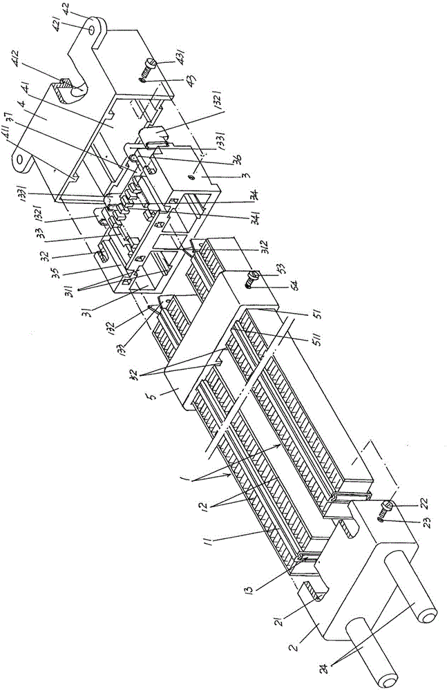
[0025] See figure 1 and image 3 , a PTC heater body 1...


PUM


Abstract

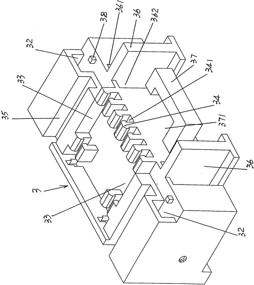
The invention provides a PTC heater and belongs to the technical field of electric heaters. The PTC heater comprises PTC heater bodies, a tailstock and an electrical connecting seat, wherein two or more PTC heater bodies are parallel and separated from one another, tailstock inserting cavities and electrical connecting seat inserting cavities identical to the PTC heater bodies in number and corresponding to positions of the PTC heater bodies are respectively formed on the tailstock and the electrical connecting seat, adjacent electrical connecting seats are separated by inserting cavity partition walls, one end of each of the PTC heater bodies facing to the electrical connecting seat is fixed with the electrical connecting seat inserting cavities in an inserting-embedding mode, one end of each of the PTC heater bodies facing to the tailstock is fixed with the tailstock inserting cavities in an inserting-embedding mode, and the electrical connecting seat is sleeved by an electrical connecting seat protective cover for protecting the electrical connecting seat. The PTC heater has the advantages of being capable of enabling two or more PTC heater bodies to share one tailstock and one electrical connecting seat, meeting the air-conditioner power change requirement, preventing an air conditioner from being limited by an installing space and meeting the flexible selection during usage.

Description

technical field [0001] The invention belongs to the technical field of electric heaters, and in particular relates to a PTC heater. Background technique [0002] The aforementioned PTC heater is also called a PTC heater, and PTC is an English abbreviation (English full name: Positive Temperature Coefficient). The PTC heater is composed of the following three parts: one is the PTC heater body, which is also called the PTC radiator body; the second is the tailstock; the third is the electrical connection seat. One end of the PTC heater body is fixed to the tailstock, and the other end is fixed to the electrical connection seat, and the PTC heater body includes an aluminum tube, and a corrugated radiator positioned on one side of the length direction of the aluminum tube or on the corresponding two sides. The aluminum sheet and the PTC heating core accommodated in the aluminum lumen of the aluminum tube, wherein the PTC heating core includes a plurality of neatly arranged and ...

Claims


Application Information

Patent Timeline
Patent Type & Authority Patents(China)
IPC IPC(8): H05B3/00H05B3/02
Inventor 刘庆新
Owner 嘉善县魏塘资产管理有限公司
Learn More