Portable display
A display and portable technology, applied in the direction of digital output to display equipment, chassis/cabinet/drawer parts, etc., can solve the problem of high miniaturization requirements, and achieve the effect of improving the degree of freedom
- Summary
- Abstract
- Description
- Claims
- Application Information
AI Technical Summary
Problems solved by technology
Method used
Image

Examples
Embodiment approach 1
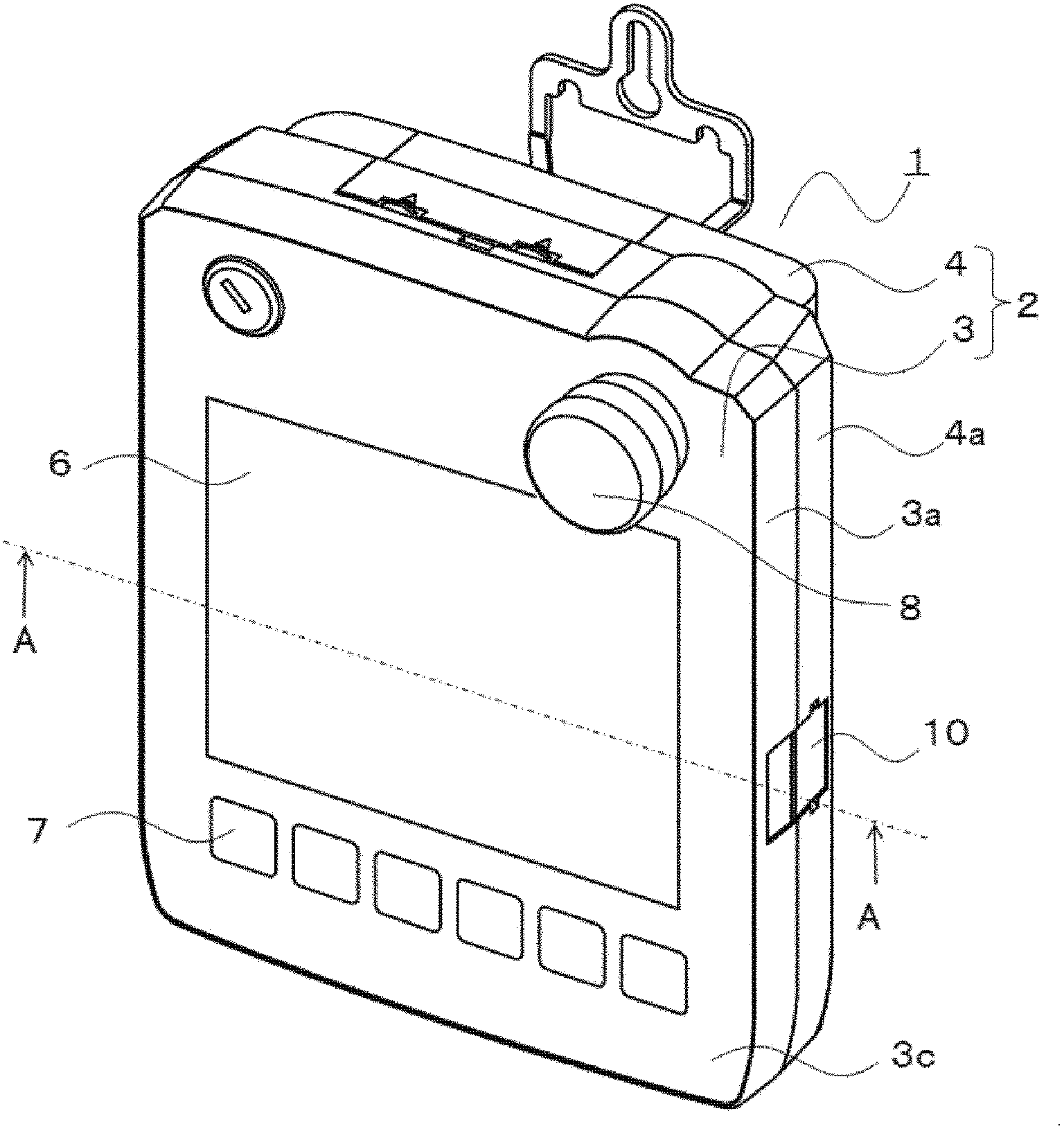
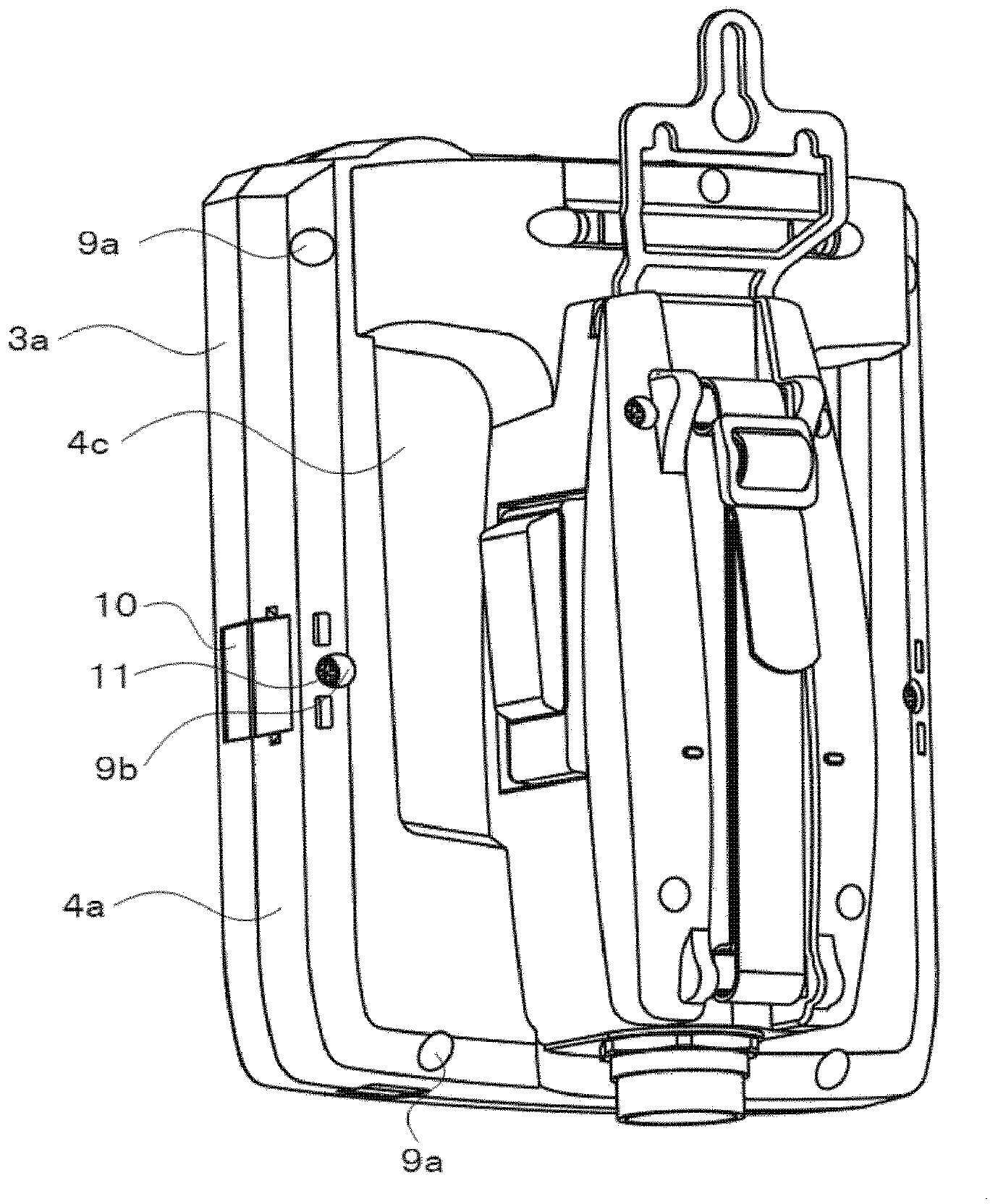
[0032] figure 1 It is a front perspective view of the portable display according to Embodiment 1 of the present invention, figure 2 It is a rear perspective view of the portable monitor. In this Embodiment 1, the portable programmable display 1 is demonstrated as a portable display.
[0033] In the figure, in the portable programmable display 1 , a casing main body 2 as a casing of the entire product is formed by a front cover 3 and a rear cover 4 . Both the front cover 3 and the rear cover 4 have side walls around them, and the joint surface 3b ( Figure 4 shown in ) and the joint surface 4b provided on the side wall 4a of the back cover 4 ( Figure 5 shown in ) via the sealing material 5 ( Figure 4 shown in ) to engage. The front cover 3 and the rear cover 4 are engaged and fixed by engaging members 10 , screw members 11 and the like. In Embodiment 1, the front cover 3 corresponds to the first housing, and the rear cover 4 corresponds to the second housing.
[0034]...
Embodiment approach 2
[0064] Next, using the sectional view of the main part i.e. Figure 9 Embodiment 2 of the present invention will be described. Embodiment 2 is a structure in which one end 10b of the engaging member 10 is engaged with the front surface 3c of the front cover 3. Except for the structure related to this structure, it is the same as Embodiment 1, and thus description thereof will be omitted. Next, points different from Embodiment 1 will be described in detail.
[0065] Figure 8 One end 10b of the middle engaging member 10 engages with the engaging portion 32a formed on the side surface 3d of the front cover 3, and Figure 9 Among them, one end 10b of the engaging member 10 engages with an engaging portion 32b formed on the front surface 3c of the front cover 3 . Figure 8 In order to provide the engaging portion 32a on the side 3d, a groove needs to be provided on the side 3d, and the thickness of the side wall 3a of the front cover 3 increases accordingly. However, Figure 9...
Embodiment approach 3
[0068] Next, using the sectional view of the main part i.e. Figure 10 , Embodiment 3 of the present invention will be described below. Embodiment 3 is a structure in which one end of an engaging member is formed into a hook shape and engages with an engaging portion, and is the same as Embodiment 1 except for the structure related to this structure.
[0069] Figure 8 Among them, the engaging portion 32a and the one end 10b of the engaging member 10 have a structure having inclined surfaces facing each other, but Figure 10 Among them, the protruding end of one end 10 b of the engaging member 10 is formed in a hook shape protruding toward the joint surface 3 b of the front cover 3 . The engaging portion 32a facing the one end 10b is formed in a concave shape opening toward the front surface 3c of the front cover 3, and is fitted with the protruding end of the one end 10b. According to this structure, when fastening is performed with the screw member 11, the engaging part 3...
PUM
 Abstract
Description
Claims
Application Information
 - R&D
- Intellectual Property
- Life Sciences
- Materials
- Tech Scout
- Unparalleled Data Quality
- Higher Quality Content
- 60% Fewer Hallucinations
Browse by: Latest US Patents, China's latest patents, Technical Efficacy Thesaurus, Application Domain, Technology Topic, Popular Technical Reports.
© 2025 PatSnap. All rights reserved.Legal|Privacy policy|Modern Slavery Act Transparency Statement|Sitemap|About US| Contact US: help@patsnap.com