Material connection device of punch press
A material splicing device and punching machine technology, which is applied in the field of punching machines, can solve the problems of manually picking and placing workpieces, falling, and not solving parts, etc., and achieves the effects of simple and practical structure, improved material splicing efficiency and high safety.
- Summary
- Abstract
- Description
- Claims
- Application Information
AI Technical Summary
Problems solved by technology
Method used
Image

Examples
Embodiment 1
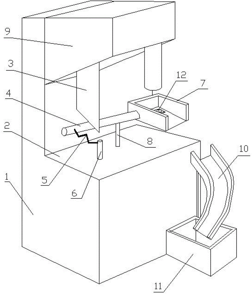
[0025] Combine figure 1 : A material receiving device for a punching machine, involving a punching machine 1, including a worktable 2, a wedge plate 3, a cross bar 4, a spring 5, a fixed rod 6, a material receiving groove 7, a support rod 8, a punching mechanism 9; a wedge plate The wider end of 3 is connected to the punching mechanism 9 of the punching machine 2, and the narrower end is downward. One end of the cross bar 4 is connected to the receiving groove 7, and the other end is connected to the spring 5 and is located below the wedge plate 3. The receiving groove 7 is placed under the punching mechanism 9. One end of the support rod 8 is fixedly connected to the middle of the cross bar 4, and the other end is movably connected to the workbench 2; one end of the fixed rod 6 is connected to the workbench 2 and the other end is connected to the spring 5. connection.
[0026] The receiving trough 7 includes a bottom wall, a rear wall, left and right walls, and the top is open; ...
Embodiment 2
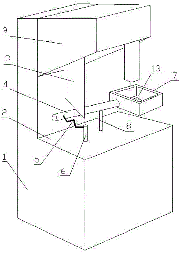
[0033] Combine figure 2 : A material receiving device for a punching machine, involving a punching machine 1, including a worktable 2, a wedge plate 3, a cross bar 4, a spring 5, a fixed rod 6, a material receiving groove 7, a support rod 8; the wedge plate 3 is wider One end is connected to the punching mechanism 9 of the punching machine 2, the narrower end is downward, one end of the cross bar 4 is connected to the receiving groove 7, the other end is connected to the spring 5, and is located below the wedge plate 3, the receiving groove 7 Placed below the punching mechanism 9, one end of the support rod 8 is movably connected to the middle of the cross bar 4, and the other end is fixedly connected to the worktable 2; one end of the fixed rod 6 is connected to the worktable 2 and the other end is connected to the spring 5;
[0034] The receiving trough 7 includes a bottom wall, a front wall, a rear wall, and left and right walls, and the top is open.
[0035] The bottom wall i...
PUM
 Abstract
Description
Claims
Application Information
 - Generate Ideas
- Intellectual Property
- Life Sciences
- Materials
- Tech Scout
- Unparalleled Data Quality
- Higher Quality Content
- 60% Fewer Hallucinations
Browse by: Latest US Patents, China's latest patents, Technical Efficacy Thesaurus, Application Domain, Technology Topic, Popular Technical Reports.
© 2025 PatSnap. All rights reserved.Legal|Privacy policy|Modern Slavery Act Transparency Statement|Sitemap|About US| Contact US: help@patsnap.com