Eureka AIR delivers breakthrough ideas for toughest innovation challenges, trusted by R&D personnel around the world.

Plate cutting system

A cutting system and plate technology, applied in metal sawing equipment, metal processing equipment, manufacturing tools, etc., can solve the problems that the sawing machine cannot be equipped with fixing or clamping devices, long adjustment time, low pass rate, etc.

Active Publication Date: 2014-09-24
北新建材(苏州)有限公司
View PDF6 Cites 14 Cited by
  • Summary
  • Abstract
  • Description
  • Claims
  • Application Information

AI Technical Summary

Problems solved by technology

However, the size adjustment between the saw blades is all manually adjusted, that is, when adjusting the size of the saw board, the screw of the motor foot fixing plate with the saw blade must be loosened, and then use a hammer according to the size required by the saw board Lightly hit the motor foot fixing plate until it is of the right size, and then tighten the fixing screws. Often this work takes at least half a shift to complete, and the adjustment time is very long. , the screws of the motor foot fixing plate become loose, the size between the saw blades changes, and the size of the plate will deviate during the cutting process, resulting in many unqualified plates
[0003] In addition, when the plate needs to be cut horizontally and vertically for multiple times, the sawing machine has no or no fixing or clamping device in the vertical direction, and it is easy to deviate during vertical cutting, the size deviation is too large, and the pass rate is low. Lower input-output ratio

Method used


Image

  • Plate cutting system
  • Plate cutting system
  • Plate cutting system

Examples


Embodiment Construction

[0054] Embodiments of the present application will be described in detail below in conjunction with the accompanying drawings. It should be noted that, in the case of no conflict, the embodiments in the present application and the features in the embodiments can be combined arbitrarily with each other.

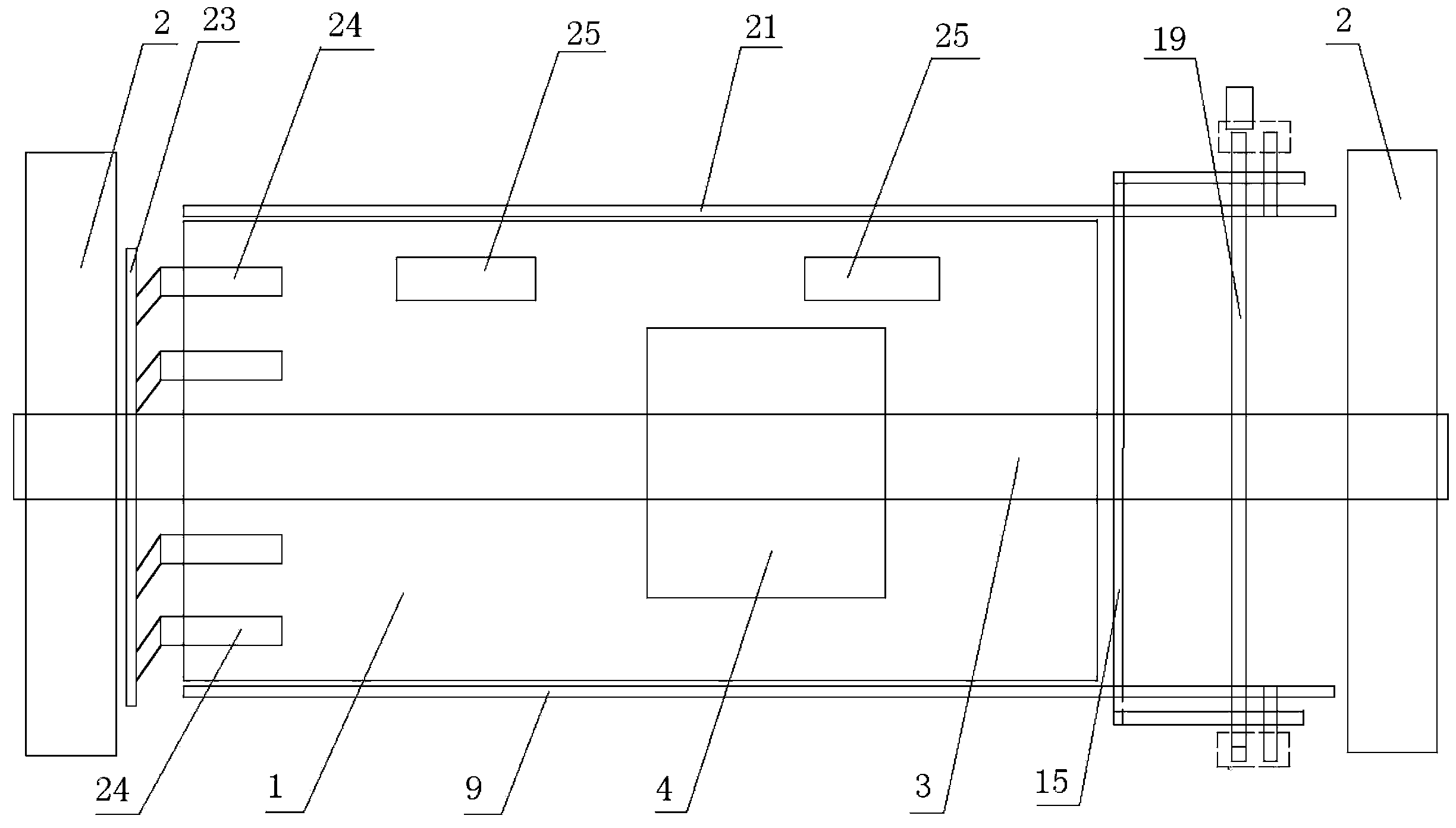
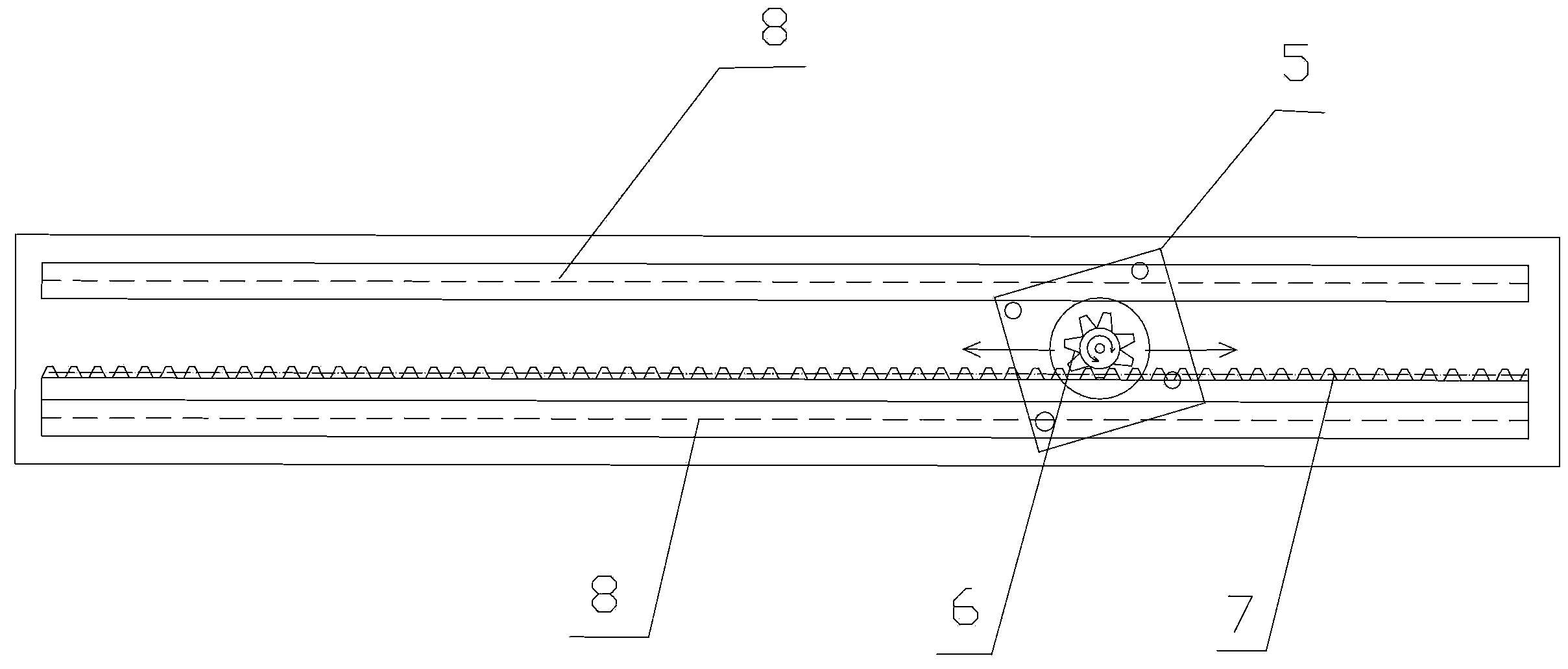
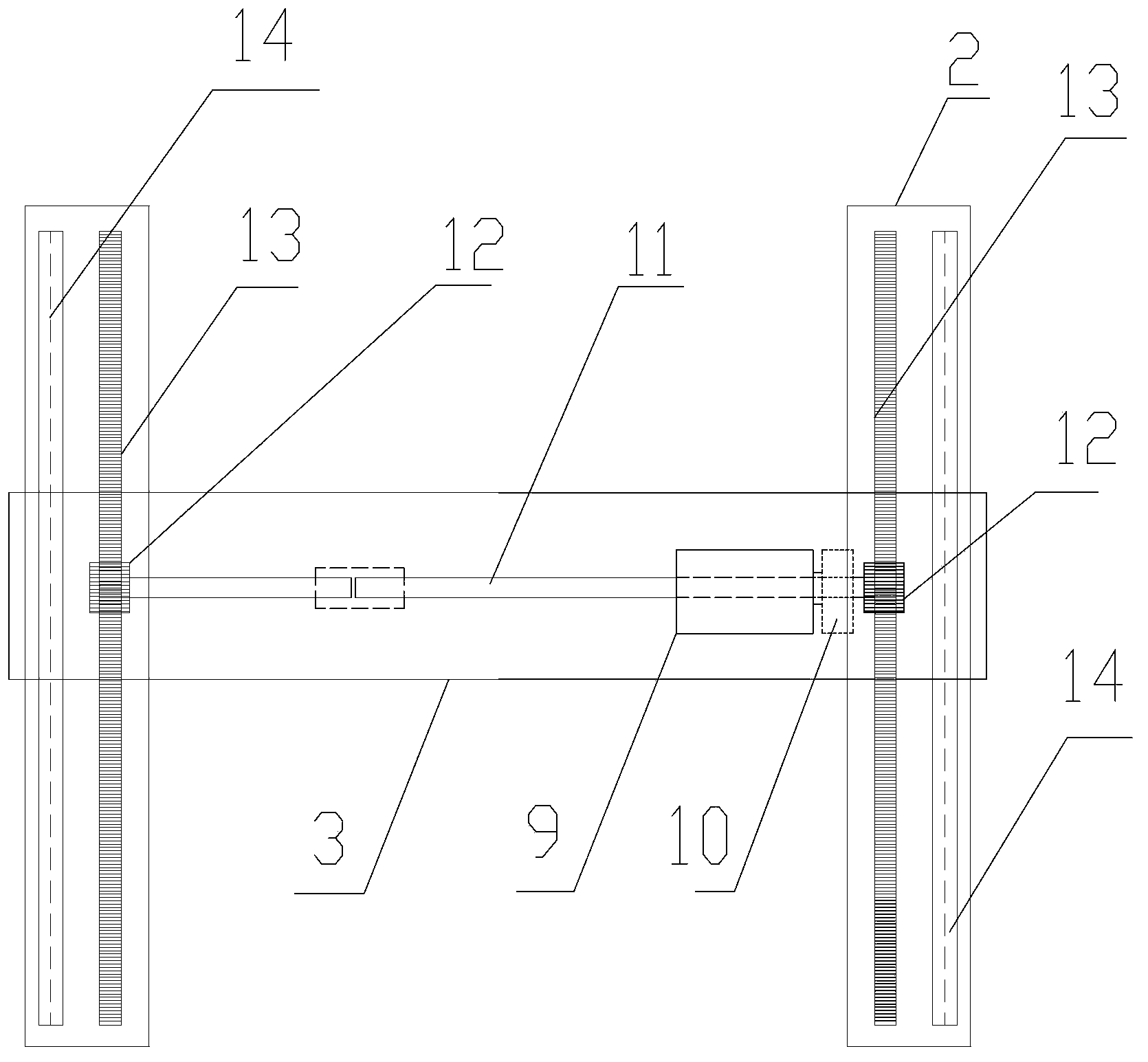
[0055] The cutting system of the sheet material of the present application is illustrated below in conjunction with accompanying drawing, as figure 1 As shown, the plate cutting system includes: a working platform 1, a first driving device, a second driving device, a cutting device, a longitudinal pressure beam 15 and a central control unit; the central control unit provides a cutting position according to the cutting size of the plate, and the cutting position includes longitudinal The cutting position and the transverse cutting position, the first driving device drives the cutting device to move laterally to the longitudinal cutting position according to the control signal o...


PUM


Abstract

The invention discloses a plate cutting method. A plate cutting system comprises first driving equipment, second driving equipment, longitudinal press beams, a cutting device and a central control unit. The plate cutting method comprises the steps as follows: the central control unit provides a longitudinal cutting position and a longitudinal fixing position according to a plate cutting size; the central control unit controls the second driving equipment to drive the longitudinal press beams to be transversely moved to two sides of the longitudinal cutting position and pressed against a plate; the central control unit controls the first driving equipment to drive the cutting device to be transversely moved to the longitudinal cutting position and controls the first driving equipment to drive the cutting device to be longitudinally moved to finish longitudinal cutting of the plate. The cutting system is applicable to plate fixation during repeated longitudinal cutting and repeated transverse cutting, and defects that the deviation occurs easily and size deviations are too large during longitudinal cutting due to the fact that no fixing device or clamping device exists or can be arranged longitudinally in the prior art are overcome.

Description

technical field [0001] The invention relates to a cutting system, in particular to a board cutting system. Background technique [0002] In related technologies, in order to cut the board (such as gypsum board) into multiple boards, the board cutting machine is sometimes provided with multiple rows of saw blades on the sawing machine, and a certain distance is set between the saw blades. sheet, so as to realize the cutting of the plate. However, the size adjustment between the saw blades is all manually adjusted, that is, when adjusting the size of the saw board, the screw of the motor foot fixing plate with the saw blade must be loosened, and then use a hammer according to the size required by the saw board Smashing the fixing plate of the motor foot lightly until it reaches the proper size, and then tightening the fixing screws usually takes at least half a shift to complete the work, and the adjustment time is very long. , The screws of the motor anchor plate are loose,...

Claims


Application Information

Patent Timeline
IPC IPC(8): B23D47/08B23D47/04
Inventor 顾云岳李华果春华
Owner 北新建材(苏州)有限公司
Why Eureka
Eureka Blog
Learn More