
Speed Control Device Of Engine

A technology of speed regulating device and engine, which is applied in the direction of engine control, machine/engine, mechanical equipment, etc. It can solve the problems of no increase in fuel volume, insufficient engine output, and hindered swing, so as to increase fuel volume and prevent insufficient engine output , The effect of absorbing size errors

Active Publication Date: 2014-09-24
KUBOTA LTD
View PDF5 Cites 0 Cited by
  • Summary
  • Abstract
  • Description
  • Claims
  • Application Information

AI Technical Summary

Problems solved by technology

[0007] PROBLEM: Insufficient engine output when load increases at low speeds
[0008] pass Figure 12 It can be seen that when the speed lever 101 is operated to stop the engine, the engaging pin P of the speed governor lever 103 is pressed by the speed regulating lever 101 that is swinging to the side of the engine stop position 106, thereby, the speed governor lever 103 is pressed by the speed regulating lever. 101 is pressed in the fuel amount decreasing direction L, and the fuel amount adjusting part 105 moves to the no-fuel supply position 107. Therefore, there is a case where the engaging part moves in the fuel amount increasing direction R when the load increases in the low-speed running state. The pin P is in contact with the governor lever 101, and the swing of the governor lever 103 in the fuel quantity increasing direction R is hindered, so that the fuel quantity does not increase, and the engine output becomes insufficient.

Method used


Image

  • Speed Control Device Of Engine
  • Speed Control Device Of Engine
  • Speed Control Device Of Engine

Examples


Embodiment Construction

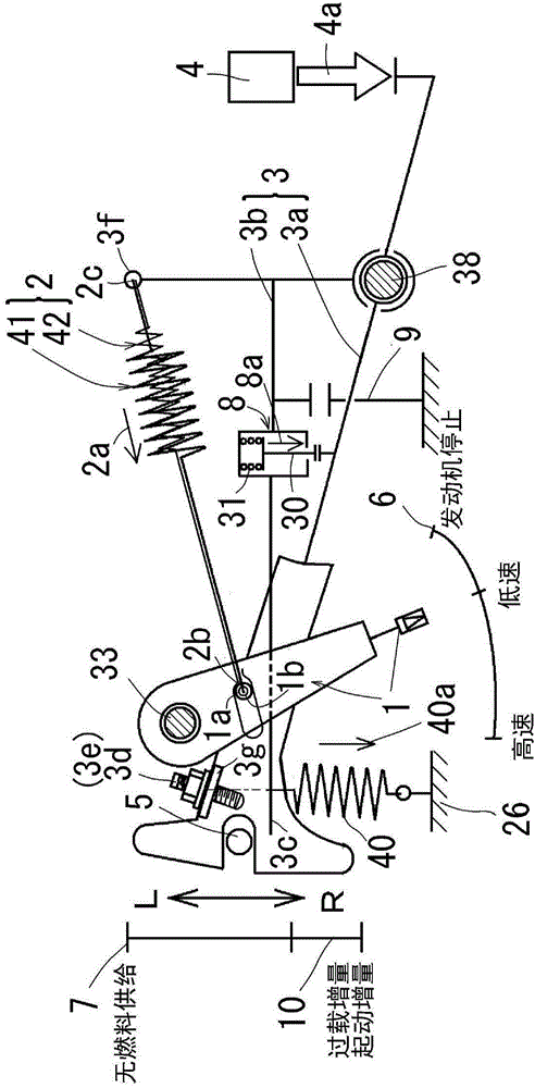
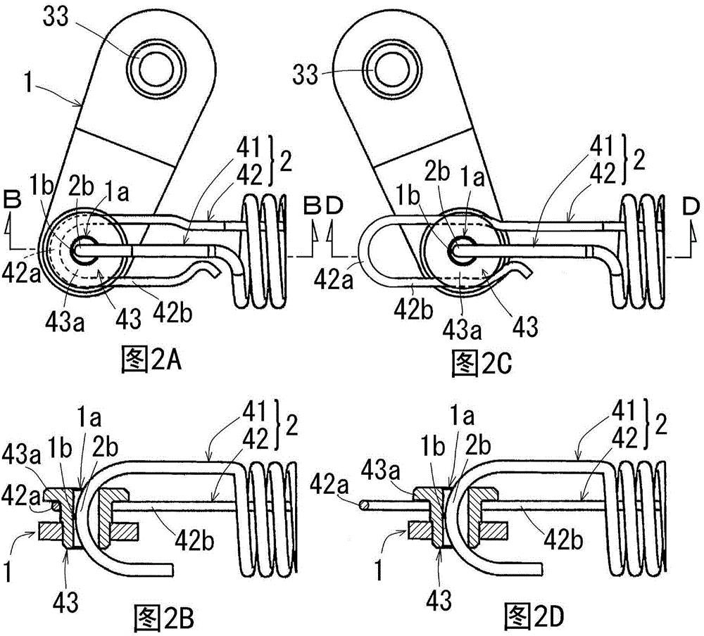
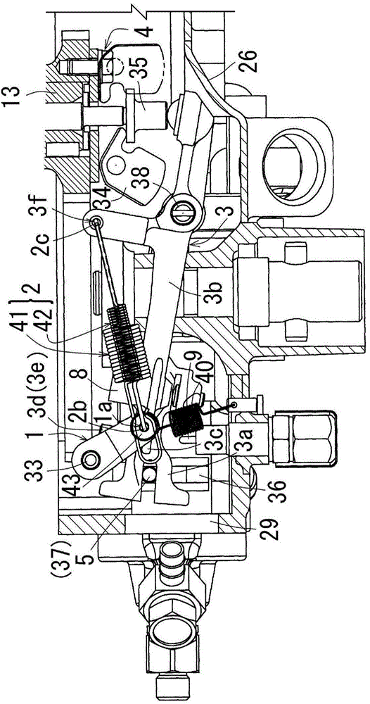
[0121] Figure 1 to Figure 6 It is a figure explaining the governor device of the diesel engine which concerns on the 1st Embodiment of this invention, Figure 7A to Figure 7F It is a figure explaining the governor device of the diesel engine of 2nd Embodiment, Figure 8A to Figure 8F It is a figure explaining the governor device of the diesel engine of 3rd Embodiment, Figure 9 ~ Figure 11 It is a figure explaining the governor of the diesel engine of 4th Embodiment, In each embodiment, the governor of a horizontal single-cylinder diesel engine is demonstrated.

[0122] First, a first embodiment will be described.

[0123] The outline of this engine is as follows.

[0124] Such as Figure 6 As shown, viewed along a direction parallel to the crankshaft central axis 11, under a specific viewing posture where the cylinder 12 faces horizontally on the left side of the crankshaft central axis 11, rotational balancers 14a, 14b are disposed on the upper right and lower right of ...


PUM


Abstract

The invention provides a speed control device of an engine and the speed control device can prevent the following conditions that inadequate output is caused to the engine when load is added at a low-speed operation state. The speed control device of the engine is structured in a way that a speed controller rod is linked with a speed control rod via a speed control spring; a speed controller force generator is linked with the speed controller rod; with imbalanced force between speed controller spring force of the speed controller spring and speed controller force generated by the speed controller force generator, the speed controller rod swings and adjusts a fuel amount adjusting part linked with the speed controller rod; when the engine is stopped via the speed controller rod, the compressed speed controller spring is pressed by the speed controller rod swinged to a stop position of the engine due to swinging operation; the speed controller rod is pressed in a direction from the speed controller spring to a fuel amount reducing direction; and the fuel adjusting part is moved to a non-fuel supplying position.

Description

technical field [0001] The present invention relates to a speed control device for an engine, and more particularly, to a speed control device for an engine capable of preventing the disadvantage that the output of the engine is insufficient when the load increases in a low-speed operation state. Background technique [0002] Conventionally, as a speed control device of an engine, the following devices exist (for example, refer to Patent Document 1). [0003] Such as Figure 12 As shown, a speed regulating device of an engine is constituted as follows: the speed governor rod 103 is linked with the speed governor rod 101 through the speed governor spring 102, the speed governor force generating device 104 is linked with the speed governor rod 103, and the speed governor The lever 103 swings by using the unbalanced force between the governor spring force 102a of the governor spring 102 and the governor force 104a of the governor force generating device 104 to adjust the amount...

Claims


Application Information

Patent Timeline
Patent Type & Authority Applications(China)
IPC IPC(8): F02D1/02
Inventor 梶原崇弘川原稔泉进刚松本刚江田悠也岩崎信吉
Owner KUBOTA LTD
Learn More