
Chain guide

A technology of chains and guides, which is applied to belts/chains/gears, mechanical equipment, transmission devices, etc., can solve the problems of material waste, increased manufacturing costs, and increased manufacturing hours, so as to reduce manufacturing costs, reduce material waste, reduce The effect of small footprint

Active Publication Date: 2014-08-27
TSUBAKIMOTO CHAIN CO
View PDF12 Cites 2 Cited by
  • Summary
  • Abstract
  • Description
  • Claims
  • Application Information

AI Technical Summary

Problems solved by technology

[0014] In such a known chain guide, since the base member 520 is formed by bending two integral metal plates by 90° to form the guide block support portion 521 and the two mounting portions 522, it is necessary to perform two steps on one metal plate. There is a problem of increased manufacturing man-hours for bending processing above the
[0015] In addition, since the guide block supporting portion 521 and the two mounting portions 522 are formed by an integral metal plate, a large amount of metal material is required, and the protruding portion is relatively large when manufactured from a single metal plate by punching or the like. There are many contour shapes, so there is a problem that material waste also increases
[0016] In addition, for example, even when many other factors are the same but only the positions of the mounting shafts B1 and B2 are different, it is necessary to design a base member 520 of a completely different shape. For 520, it is necessary to punch different shapes, and the position for bending processing also needs to be different. Therefore, when the design of the installation object is changed, or when it is applied to various installation objects, there is a lack of versatility and manufacturing costs. additional questions
[0017] In addition, when forming the mounting portion on the base member, the material and thickness must be the same, and it is difficult to perform an optimal design for each, and there is a problem that the material cost cannot be reduced.

Method used


Image

  • Chain guide
  • Chain guide
  • Chain guide

Examples


Embodiment 1

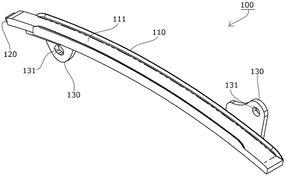
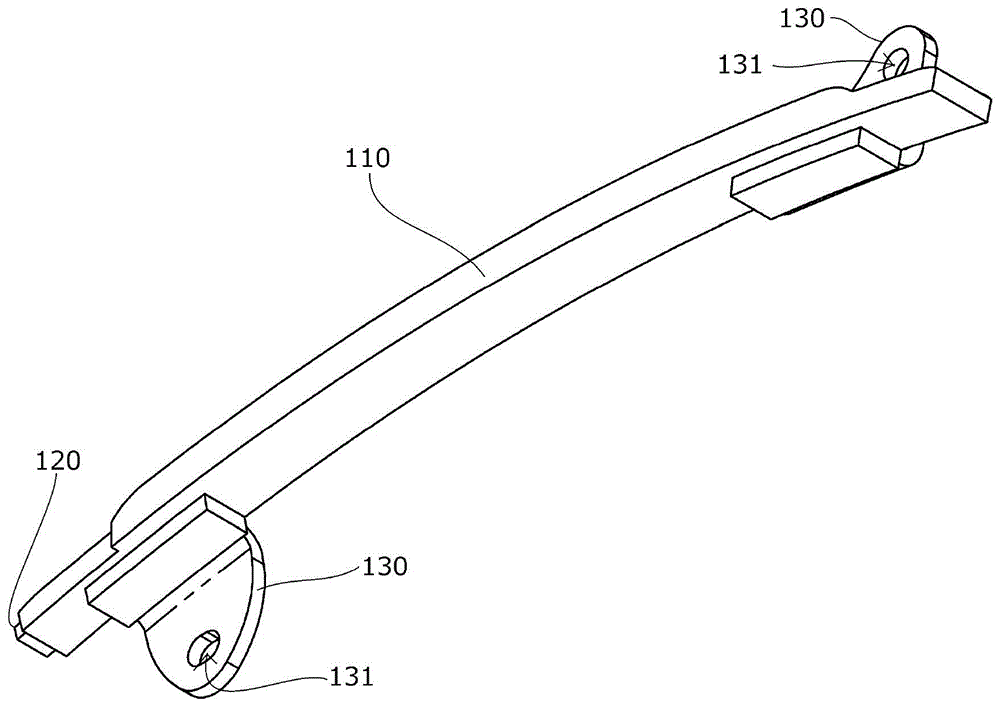
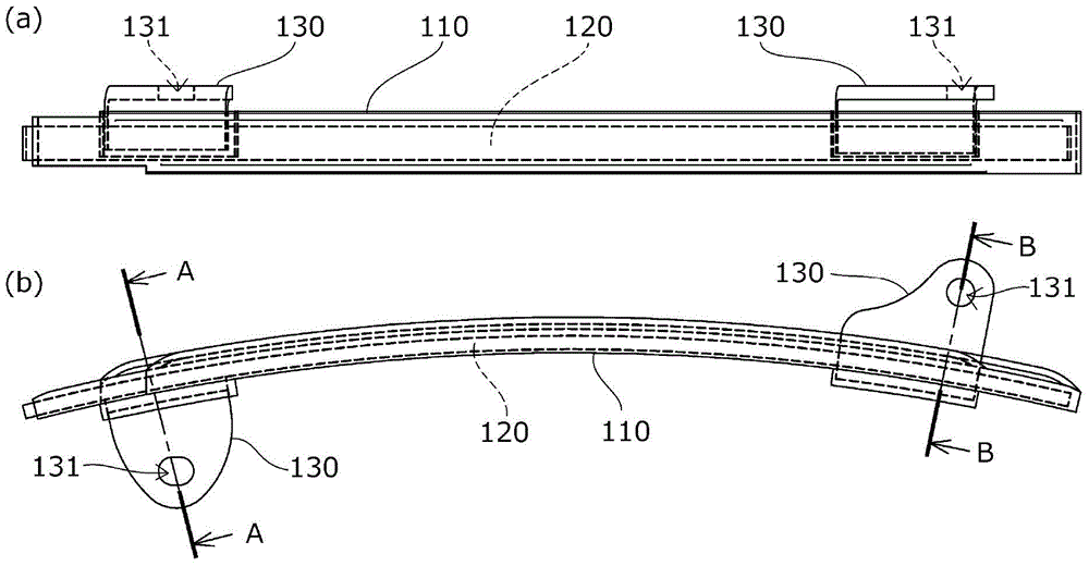
[0112] The chain guide 100 (fixed guide) according to the first embodiment of the present invention will be described with reference to the drawings.

[0113] The chain guide 100 is a chain guide suitable for the aforementioned known timing systems, such as Figure 1 to Figure 5 As shown, it is provided with: a guide block 110, which slides and guides the moving chain; and a base member 120, which reinforces the guide block 110 along the moving direction of the chain.

[0114] The base member 120 extends in the chain movement direction while having a predetermined curved shape along the chain movement direction, and is formed, for example, by punching out of one rolled steel plate.

[0115] The mounting member 130 is formed separately from the guide block 110 and the base member 120 and has: a mounting portion 133;

[0116] Mounting holes 131 are provided in the mounting portion 133 through which bolts and the like are inserted and fixed to an engine compartment or the like. ...

Embodiment 2

[0126] like Figure 6 to Figure 8 As shown, the chain guide 100A according to the modified example of the first embodiment of the present invention is as follows, the fixing piece 132A of the mounting member 130A is provided with the filling hole 134 filled with the material of the guide block 110, and the other structure is the same as that of the aforementioned first The chain guide 100 according to the first embodiment is the same (the same reference numerals are given to the same members as those of the chain guide 100 , and the perspective view is omitted because it is the same as that of the chain guide 100 ).

[0127] As a result, when the guide block 110 is formed by injection molding or the like in a state where the base member 120 and the fixing piece 132A of the attachment member 130A are inserted, a chain that more reliably fixes the guide block 110 , the base member 120 , and the attachment member 130A can be obtained. 100 A of guides can exhibit the same special ...

Embodiment 3

[0129] like Figure 9 to Figure 12 As shown, the chain guide 100B according to another modified example of the first embodiment of the present invention is as follows. The base member 120 and the fixing piece 132 of the mounting member 130 are previously fixed and integrated by an appropriate method such as spot welding, and the guide block 110B engages with the base member 120 to form an integrated fixed guide block 110B, base member 120, and mounting member 130. Other structures are the same as those of the chain guide 100 according to the first embodiment described above (the same as the chain guide 100). components marked with the same symbol).

[0130] Like the aforementioned known guide block 510, the guide block 110B of this modified example is constituted as follows. End locking pieces 112 are respectively provided at both ends in the chain movement direction, and a plurality of side locking pieces 112 are provided at appropriate positions in the width direction. The ...


PUM


Abstract

There is provided a chain guide that reduces a space occupied by the chain guide in an engine room while maintaining required strength, rigidity, and durability with a simple configuration, reduces the number of manufacturing steps and the waste of a material, does not require a structure that permits an error, prevents increases in vibration and noise during use, and reduces the burden of a maintenance operation. The chain guide has a guide shoe and a base member that reinforces the guide shoe, and an attachment portion includes an attachment member that is provided separately from the guide shoe and the base member and can be fixed to at least one of the guide shoe and the base member or both of the guide shoe and the base member.

Description

technical field [0001] The invention relates to a chain guide, which comprises: a guide block, which slides and guides a moving chain; a base member, which reinforces the guide block along the chain movement direction; and at least one installation part. Background technique [0002] Conventionally, in order to stabilize and properly maintain the tension of the chain moving between the sprockets, a chain guide provided with a guide block for slidingly guiding the moving chain is generally used. [0003] For example, if Figure 64 As shown, the following timing system is known, which is a transmission such as a roller chain that performs seamless rotation between the sprockets S1, S2, and S3 of the crankshaft and the camshaft respectively arranged in the engine room (engine room). The timing system of the engine in which the chain CH moves, and the timing chain CH rotates seamlessly between the driving sprocket S1 of the crankshaft installed in the engine room E and a pair of...

Claims


Application Information

Patent Timeline
Patent Type & Authority Applications(China)
IPC IPC(8): F16H7/18
CPCF16H7/18
Inventor 榑松勇二中久保克也小川岳志
Owner TSUBAKIMOTO CHAIN CO
Learn More