Chain guide

A chain and guide technology, applied in belts/chains/gears, mechanical equipment, transmissions, etc., can solve problems such as breakage, increased manufacturing time, material waste, etc., to reduce occupied space, simplify manufacturing processes, and reduce manufacturing. cost effect

Inactive Publication Date: 2014-08-06
TSUBAKIMOTO CHAIN CO
View PDF8 Cites 4 Cited by
  • Summary
  • Abstract
  • Description
  • Claims
  • Application Information

AI Technical Summary

Problems solved by technology

[0014] In such a known chain guide, in order to improve the strength, rigidity, and durability of the base member 520, it is necessary to form it from a relatively thick metal plate by punching, which requires a relatively large processing machine and increases the processing cost. The problem
[0015] In addition, there is a problem that when the base member 520 is punched out from the metal plate, burrs remain on the cut surface, and the burrs contact the guide block 510 to generate minute scratches, which become stress concentration points and cause damage. opportunity
[0016] In addition, since the base member 520 is formed by bending two integral metal plates by 90° to form the guide shoe support portion 521 and the two mounting portions 522, two bending processes are required, and there is a problem that the manufacturing man-hours increase.
[0017] In addition, since the guide block supporting portion 521 and the two mounting portions 522 are constituted by an integral metal plate, a large amount of metal material is required, and since a protrusion is formed when it is manufactured by punching or the like from a single metal plate, Because of the contour shape with many parts, there is a problem that material waste also increases

Method used


Image

  • Chain guide
  • Chain guide
  • Chain guide

Examples


Embodiment 1

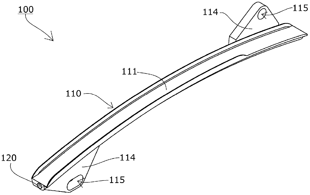
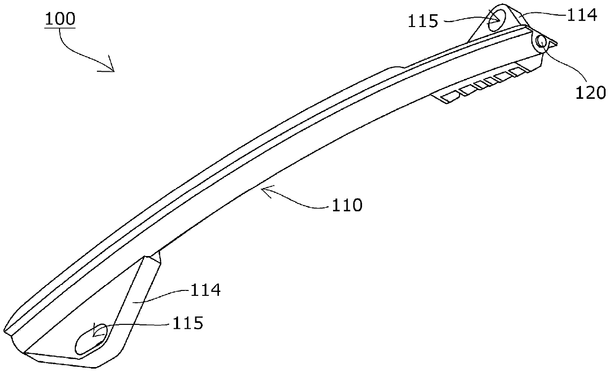
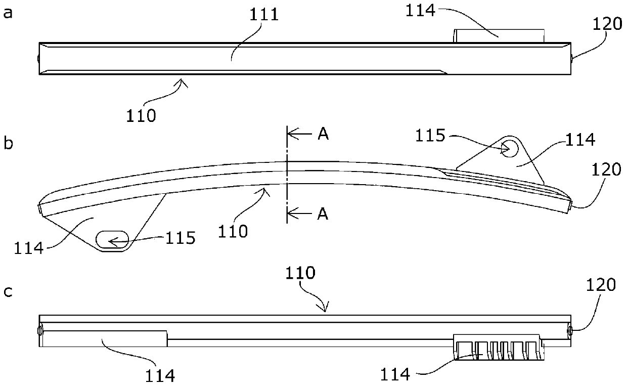
[0067] The chain guide 100 (fixed guide) according to the first embodiment of the present invention will be described with reference to the drawings.

[0068] The chain guide 100 is a chain guide suitable for the aforementioned known timing systems, such as Figure 1 to Figure 4 As shown, there are: a guide block 110, which slides and guides the moving chain; and a base member 120, which reinforces the guide block 110 along the chain movement direction to improve strength, rigidity, and durability.

[0069] The base member 120 is formed of a metal rod extending in the chain movement direction, and is formed, for example, by drawing a steel material and cutting it to an appropriate length.

[0070] In addition, the base member 120 has a prescribed curved shape along the chain moving direction.

[0071] The guide block 110 has a motion guide portion 111 extending in the chain motion direction, is formed of a synthetic resin material, and is integrally molded with the base membe...

Embodiment 2

[0086] A chain guide 200 (fixed guide) according to a second embodiment of the present invention will be described with reference to the drawings.

[0087] The chain guide 200 is a chain guide suitable for the aforementioned known timing systems, such as Figure 7 to Figure 10 As shown, it has: a guide block 210, which slides and guides the moving chain; and a base member 220, which reinforces the guide block 210 along the chain movement direction to improve strength, rigidity, and durability.

[0088] The guide block 210 has a movement guide portion 211 extending in the chain movement direction, is formed of a synthetic resin material, and is integrally formed by, for example, injection molding with the middle portion of the base member 220 inserted therein.

[0089] The base member 220 is formed of a metal rod extending in the chain movement direction, and is formed, for example, by drawing a steel material and cutting it to an appropriate length.

[0090] Both end portions...

Embodiment 3

[0110] A chain guide 300 (swing guide) according to a third embodiment of the present invention will be described with reference to the drawings.

[0111] The chain guide 300 is a chain guide suitable for the aforementioned known timing systems, such as Figure 15 to Figure 18 As shown, it is equipped with: a guide block 310, which swings around the mounting hole 315, and slides and guides the moving chain; durability.

[0112] The base member 320 is formed of a metal rod extending in the direction in which the chain moves, and is formed, for example, by drawing a steel material and cutting it to an appropriate length.

[0113] In addition, the base member 320 has a prescribed curved shape along the moving direction of the chain.

[0114] The guide block 310 is formed of a synthetic resin material, has a motion guide portion 311 extending in the direction of chain motion, and has a longitudinal wall portion 316 on the opposite side of the chain motion of the motion guide por...


PUM


Abstract

The invention provides a chain guide. By employing a simple configuration, a space required for engine room can be minimized while securing enough strength, rigidity, and durability, and a reduction in a material waste, manufacturing processes, and manufacturing cost can be accomplished while occurrence of a crack or breakage during use is prevented. A chain guide (110) includes a guide shoe (110), a base member (120) configured to reinforce the guide shoe (110), and attaching sections (114). The base member (120) is formed by a bar made of a metal material.

Description

technical field [0001] The invention relates to a chain guide, which comprises: a guide block, which slides and guides a moving chain; a base member, which reinforces the guide block along the chain movement direction; and at least one installation part. Background technique [0002] Conventionally, in order to stabilize and properly maintain the tension of the chain moving between the sprockets, a chain guide provided with a guide block for slidingly guiding the moving chain is generally used. [0003] For example, if Figure 23 As shown, the following timing system is known, which is a transmission such as a roller chain that performs seamless rotation between the sprockets S1, S2, and S3 of the crankshaft and the camshaft respectively arranged in the engine room (engine room). The timing system of the engine in which the chain CH moves, and the timing chain CH rotates seamlessly between the driving sprocket S1 of the crankshaft installed in the engine room E and a pair of...

Claims


Application Information

Patent Timeline
Patent Type & Authority Applications(China)
IPC IPC(8): F16H7/18
CPCF16H7/18F16H2007/0872
Inventor 近能雅彦森薰石川祐一郎高木雄大
Owner TSUBAKIMOTO CHAIN CO
Why Eureka
Try Eureka