Interactive projection optical system and working method thereof

An optical system and interactive projection technology, applied in the field of interactive projection, can solve problems such as complex optical path structures, and achieve the effect of avoiding the problem of wrong areas

Inactive Publication Date: 2014-09-24
SHENZHEN ANHUA OPTOELECTRONICS TECH
View PDF5 Cites 7 Cited by
  • Summary
  • Abstract
  • Description
  • Claims
  • Application Information

AI Technical Summary

Problems solved by technology

In addition, since the projection devices are usually off-axis projection, if the light utilization efficiency of the infrared lighting device is to reach a high level, that is, the infrared lighting area is uniform and the projection display area is covered with a small margin as much as possible, a more complex optical path structure is required to achieve accomplish

Method used


Image

  • Interactive projection optical system and working method thereof
  • Interactive projection optical system and working method thereof
  • Interactive projection optical system and working method thereof

Examples


Embodiment Construction

[0023] In order to make the object, technical solution and advantages of the present invention clearer, the present invention will be further described in detail below in conjunction with the accompanying drawings and embodiments. It should be understood that the specific embodiments described here are only used to explain the present invention, not to limit the present invention.

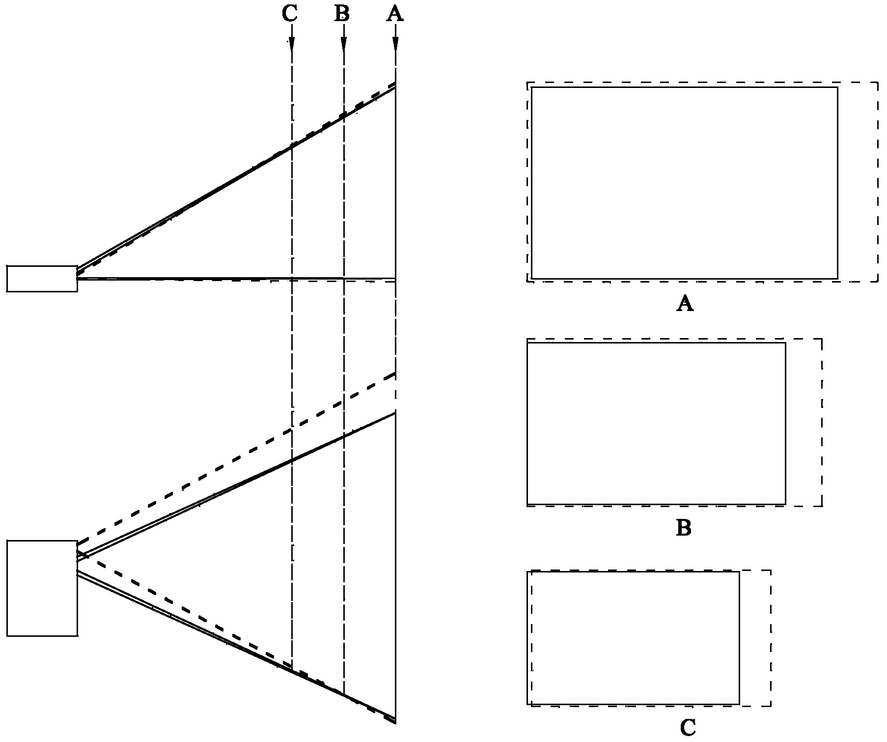
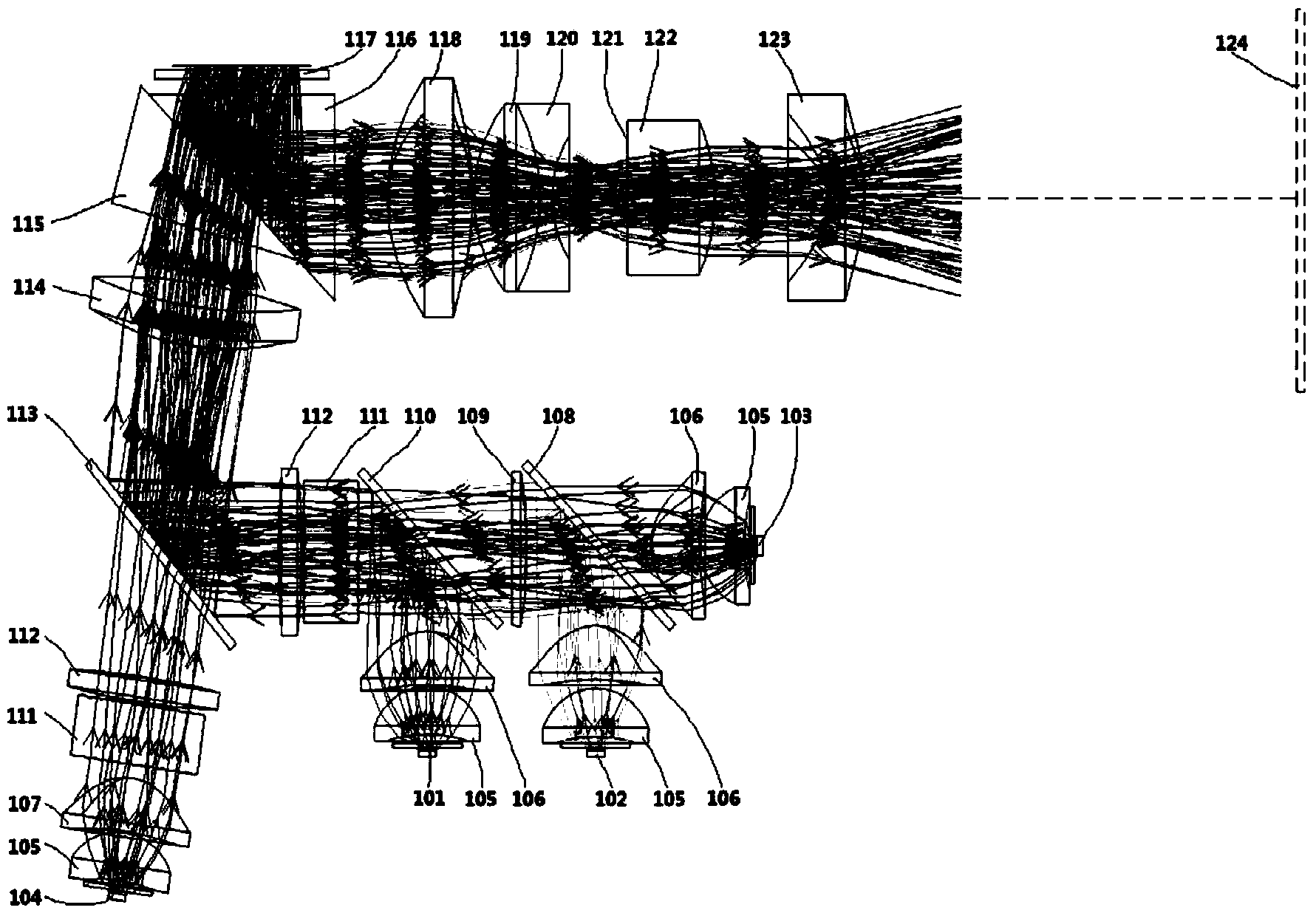
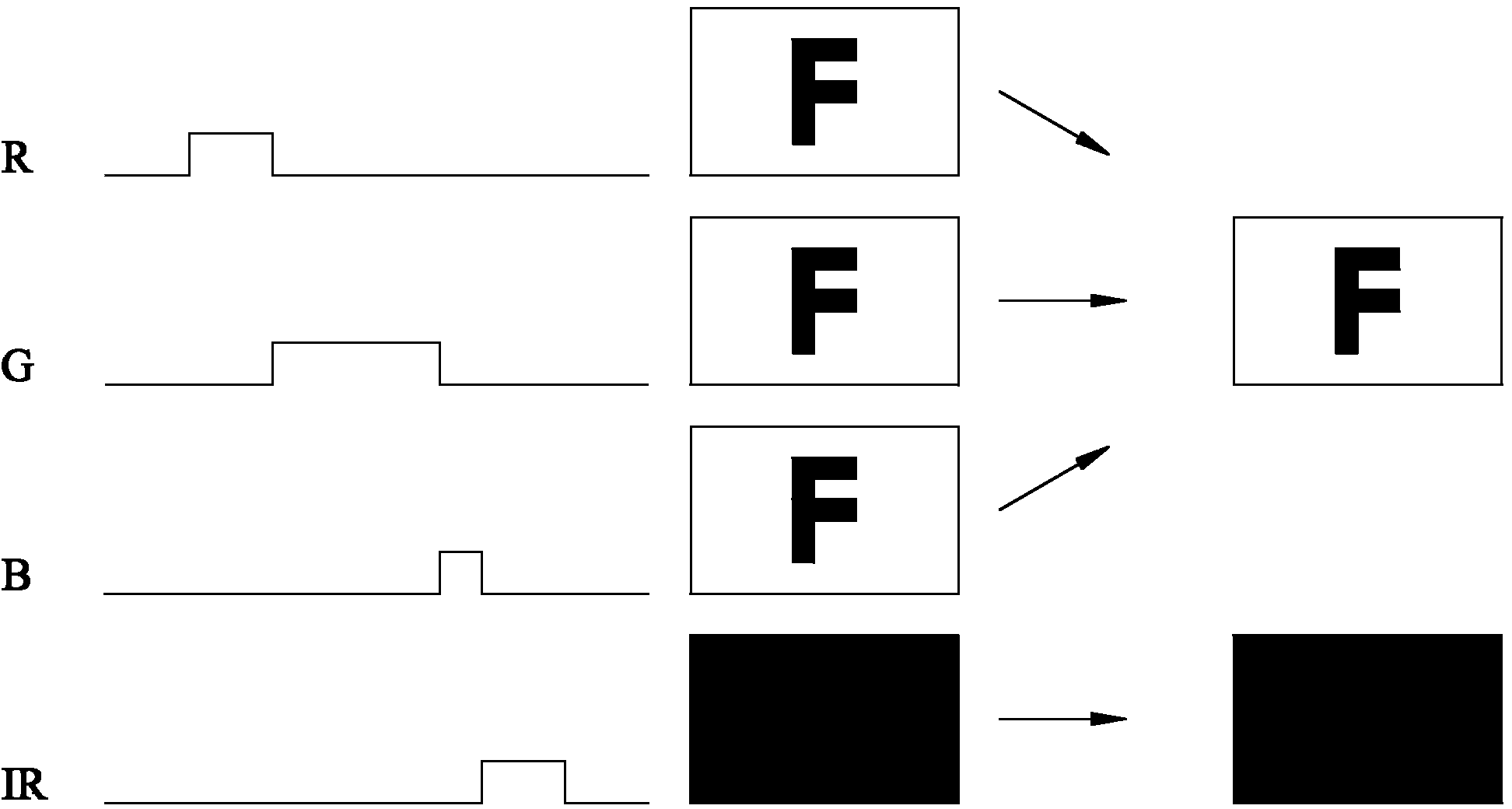
[0024] In an embodiment of the present invention, an infrared lighting device is integrated in the interactive projection optical system, and the infrared lighting device and the interactive projection optical system share the optical path of the projection optical engine; the infrared lighting area and the projection display area are completely overlapped, which can To avoid the problem of misalignment between infrared lighting and projection images under different projection distances, and for the application of interactive projection products, only the appropriate infrared camera device needs to ...


PUM


Abstract

The invention discloses an interactive projection optical system and a working method of the interactive projection optical system. The interactive projection optical system is integrated with an infrared lighting device sharing a projection optical engine optical path with the system, an infrared lighting area and a protection display area coincide completely, and area dislocation between infrared lighting and projection pictures under different projection distances can be avoided; meanwhile, optical power of a three-primary-color light source and optical power of an infrared light source are effectively utilized under the situation of low cost; in addition, an interactive projection product can be applied only by selecting a proper infrared shooting device without additionally considering matching and adjustment of the infrared lighting device.

Description

technical field [0001] The invention relates to the field of interactive projection, in particular to an interactive projection optical system and a working method thereof. Background technique [0002] In the interactive projection device of the prior art, the infrared lighting device, the projection optical engine and the infrared camera device are mutually independent modules, which are respectively assembled on the whole projector, and are adjusted so that both the infrared lighting area and the infrared camera area cover Projected display area. The infrared camera device does not image the projection display screen through the filter, and when an interactive target (person, pointer, etc.) appears in the projection display area, it will scatter infrared illumination light and be captured by the infrared camera device. [0003] For an interactive projection system in which the infrared lighting device, projection optical engine, and infrared camera device are independent...

Claims


Application Information

Patent Timeline
Patent Type & Authority Applications(China)
IPC IPC(8): G03B21/20G03B21/00
Inventor 程炎王凡王中俭朱青
Owner SHENZHEN ANHUA OPTOELECTRONICS TECH
Why Eureka
Try Eureka