Bent pipe device

A pipe bending device and pipe bending technology, which is applied in metal processing equipment, forming tools, manufacturing tools, etc., can solve the problem of less bending specifications of pipe bending, and achieve the effect of reducing precision requirements

Active Publication Date: 2015-02-25
HUZHOU MACHINE TOOL WORKS
View PDF6 Cites 6 Cited by
  • Summary
  • Abstract
  • Description
  • Claims
  • Application Information

AI Technical Summary

Problems solved by technology

[0003] The invention provides a pipe bending device to overcome the deficiencies of the prior art, and solves the problem of less bending specifications of the pipe

Method used


Image

  • Bent pipe device
  • Bent pipe device
  • Bent pipe device

Examples


Embodiment Construction

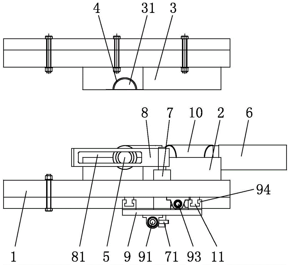
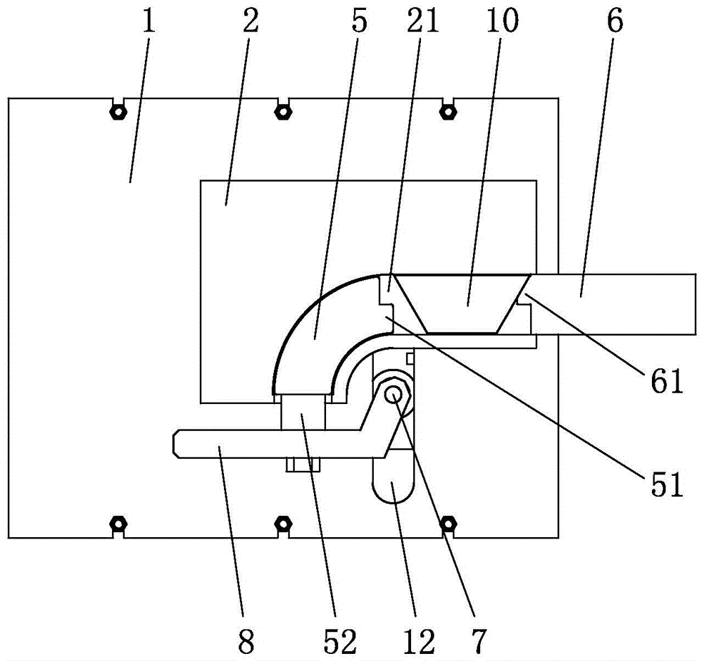
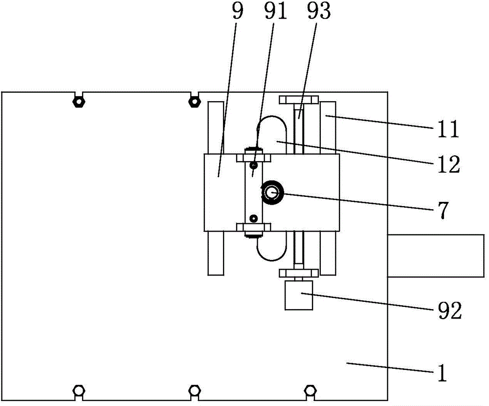
[0019] refer to figure 1 , a pipe bending device, comprising a base plate 1, the top surface of the base plate 1 is provided with a pipe bend forming die, the pipe bend forming die includes an upper die 3 and a lower die 2 fixed on the base plate 1, the upper die 3 is located at the bottom of the lower die 2 Directly above, the bottom surface of the upper mold 3 is provided with a first groove 31 with an opening downward, and the top surface of the lower mold 2 is provided with a second groove 21 with an upward opening. After the top end surface, the first groove 31 and the second groove 21 can be spliced ​​into an elbow forming cavity. The elbow forming cavity is provided with a straight section and an arc section. The port at the end of the straight section away from the arc section is the feed port, and the punch 6 moves axially through the feed port and is inserted into the elbow forming cavity. The port at one end of the section away from the straight section is the disc...


PUM


Abstract

The invention relates to a bent pipe device, and belongs to the field of bent pipe machining devices. The bend pipe device solves the problem that a bent pipe is less in bending specifications. The bent pipe device comprises a bottom plate, a punch and a bent head core rod. The bottom plate is provided with a core rod traction assembly and a detachable bent pipe forming die. The bent pipe forming die is provided with a bent pipe forming cavity. The bent pipe forming cavity comprises a feed opening and a discharge opening. The core rod traction assembly comprises a rotating shaft, a transmission rod and a drive unit. One end of the transmission rod is fixed to the rotating shaft. The other end of the transmission rod is provided with a transverse track. The bent head core rod is fixed to the transverse track and moves along the transverse track relative to the bottom plate. The bottom plate is provided with a vertical track. The rotating shaft is arranged at the vertical track. The drive unit drives the rotating shaft to move along the vertical track relative to the bottom plate. The bent head core rod conducts circumference motion along with the core rod traction assembly.

Description

technical field [0001] The invention relates to a pipe bending device, which belongs to the field of pipe bending processing devices. Background technique [0002] The existing pipe bending device includes a base plate, a mold, a punch and an elbow mandrel. The mold is installed on the base plate, and the punch pushes the straight tube that is sleeved on the elbow mandrel, so that the straight tube is bent to a radius equal to the radius of the elbow mandrel. Consistent bends. When bending pipes with different radii, the dies, punches and elbow mandrels on the bottom plate all need to be replaced. The position of the elbow mandrel on the existing bottom plate is unchanged. The bottom plate and the mold are matched by axially arranged fasteners. The bottom plate is provided with positioning holes that cooperate with the fasteners. The number and position of the positioning holes are fixed. That is to say, the mold of the existing pipe bending device can only be installed on...

Claims


Application Information

Patent Timeline
Patent Type & Authority Applications(China)
IPC IPC(8): B21D37/10B21D9/12B21D9/16
CPCB21D9/125
Inventor 周凌华钱晔陈明顾锦荣许涛
Owner HUZHOU MACHINE TOOL WORKS
Why Eureka
Try Eureka